Links
Renewable Energy Log
April 2007
27th - 12v Items
March 2007
24th - New Monitor Box
January 2007
30th - 90Ah SLA Battery
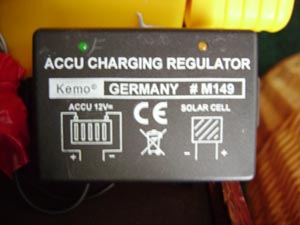
26th - New Charge Controller
10th - 18w Panel Smash
December 2006
23rd - RE Radio Shack
4th - RE Laptop
2nd - 10mm LED Torch
November 2006
21st - Panel Stand
October 2006
16th - More Portable Ideas
10th - More Portable Ideas
8th - Portable Ideas
2nd - 60w Array
September 2006
20th - 18W eBay Panel
20th - Solar Monitor Box
17th - CCFL Lights
17th - 17Ah Battery Datasheet
5th - SLA Batteries
August 2006
6th - 6W Folding Panel
Copyright © 2006-2007
Andrew Whyman
The camping project (6w folding panel):
Started April 2006:
I needed a suitable power supply for camping for when we go every year. So I decided to make my own. It consists of:
Total: Ł84
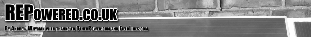
| The powerpack is a 17.2Ah lead acid battery capable of 400 cranking amps to start a car with a flat battery. | 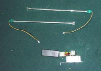
|
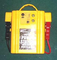
The cold cathode tubes are two 8 inch tubes. They draw about 0.5Amps each and Ive only ever used 1 at a time.
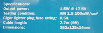
The two 1.5watt solar panels are identical and each gives out a maximum voltage of 21v open circuit and 125mA at full capacity. I can connect them in series or parallel, depending on light conditions. |
Low light - Series for more voltage 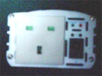
The inverter is 600watts. It draws about 50A at full load. It will be used sparingly because of the amount of current it draws.
| |
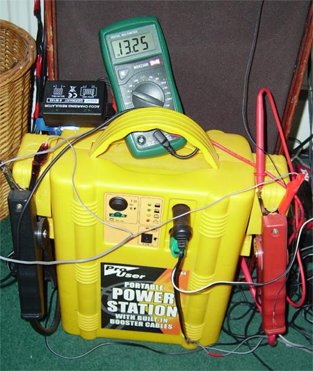
Power Pack:
17.2Ah isnt a lot but for its price of Ł18 it was worth it. It has enough power to start up to a 2.0L petrol car and up to a 1.8L diesel car. It has 2 cigarette lighter sockets on the front hidden behind a sliding panel, and a charge state display in the form of 4 LED lights. You can connect things to the jump leads too. I have to do this for the solar panels as they use crocodile clips.
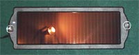
Solar Panels:
Because the solar panels give out so little current they have to be positioned for optimal use. Generally this is at a 45degree angle to the sun. Most light is collected at this angle. The maximum current I can get from each is 125mA, meaning a top current of 250mA. This is half the current of its original mains charger.
Cathodes:
I tested that the lights it will last roughly 20 hours continuous use on 1 cold cathode tube. This should be plenty for camping in May as it gets dark at around 10pm. Meaning we use the light for about 4 hours per night.
Inverter:
The inverter is a different matter. At full load (600w/50A) it will last less than 20 minutes! Using it sparingly is a necessity. Because the powerpack is a lead acid battery, letting it go flat will damage it to the point where its useless. Also, the solarpanels will not charge the powerpack very fast, especially in low light.
Lead acid battery charge level chart:
* Once at this point, the battery will start to sulphate, damaging it and preventing its ability to hold a charge.
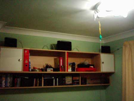
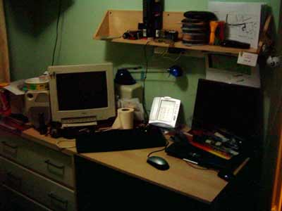
Here are some pictures to show you how bright just one of these cathode tubes is. The room was completely dark before I turned the cathode on.
June 2006:
I have recently purchased 2 additional panels to go with the original two. They are the same type but a different colour. These ones are grey. I also got a charge controller.
Camping:
I have been camping but without the additional panels (I had the controller) and the system held up for the week while I was there, approaching a critical 12.5v (12.3v under load) during the week, but this was topped up with sun as every day I managed at least 10 hours of bright sun (every day was pure sun, so I was made up). I turned the panels as each day progressed to make the best of the sun. I managed to run the cathode tube most nights but the backup LED light came into play when the voltage fell to the critical level. I also used the system to charge up my mobile phone and PDA through their "car" chargers on the ciggy lighter sockets.
More pictures:
| |||||
July 2006:
10th July:
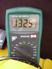
   Date/Time      Voltage Start   Voltage Finish
11/07/2006 21:12      13.22            13.02
12/07/2006 19:57      13.35            13.15
13/07/2006 20:09      13.36            -----
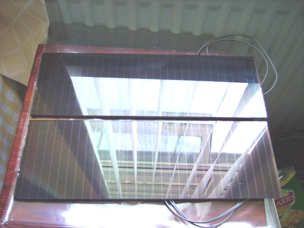
Ive disected two of the panels to I can re-mount them on some plywood. The cases were obstructing approximately 5mm each side of the panels slightly reducing their capacity. Also the LED circuit was draining around 15% of their power, which is a waste.
15th July:
Ive just received 2 more panels today. I got them half price again, so Ł20 for 2 panels. I havent done anything related to mounting the disected panels yet but I did do some testing this morning. It seems I can only get around 30mA from each panel, which I dont understand. They are supposed to give out 125mA in full sunlight, which is what we have today. Im still investigating why this is so, Im suspecting my meter could be to fault. In a full short through the meter 30mA is all I am getting. Connecting a 60mA load to it (an LED light) it works but the voltage across the terminals is around 8.5v, not 12v.
17th July:
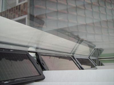
It seems the problem with not getting full capacity was caused by my double glazing. It is now against the law for glass not to be tinted to reject UV rays. This means the panels will not work to their best when behind the glass. After testing the panels outside I got the following results:
Panel 1: 63mA - A little low but this was one of the earlier panels
Panel 2: 96mA - Quite high, probably will be better if the angle is correct
Panel 3: 101mA - Great!
Panel 4: 114mA - Excellent!
Panel 5: 92mA - Good
Panel 6: 97mA - Good
It also seems my meter was about 15mA inaccurate as it showed about 15-20mA lower than another meter I have which is of better quality.
Hopefully I should get some plywood to mount the disected panels on today. I should have it completed within a few days if I get the plywood today. I disected two more panels yesterday. I now have 2 left to do which should take about an hour to remove and clean off the rubber seal.
Later on today...
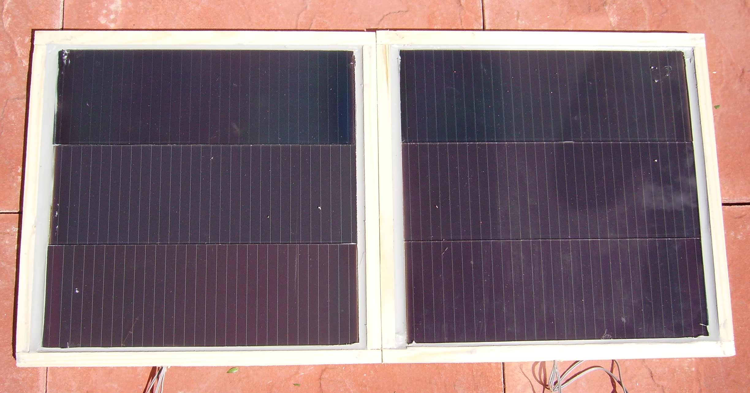
| I managed to get the plywood and Ive positioned the panels as I want them as you can see in the picture. I still have 2 more panels to disect, hence the space left for them. In total I should end up with around 9 watts but as tests have gone I think this will be more like 5-6, but this will come when its all wired up and put to the real test as a parrallel array. I am trying to decide HOW to actually mount the panels. They need to be raised slightly because of the connections and wires on the back, and the only place to mount them is on their back, so Im trying to think of a way to mount them in such a way that they wont fall off and break. I also need some hinges so I can open and close the panels like a briefcase. Remember this is supposed to be a portable setup so it needs to be neat and easily movable. I also need some way of angling them towards the sun so Ill need a stand on the back of both parts of the array. | 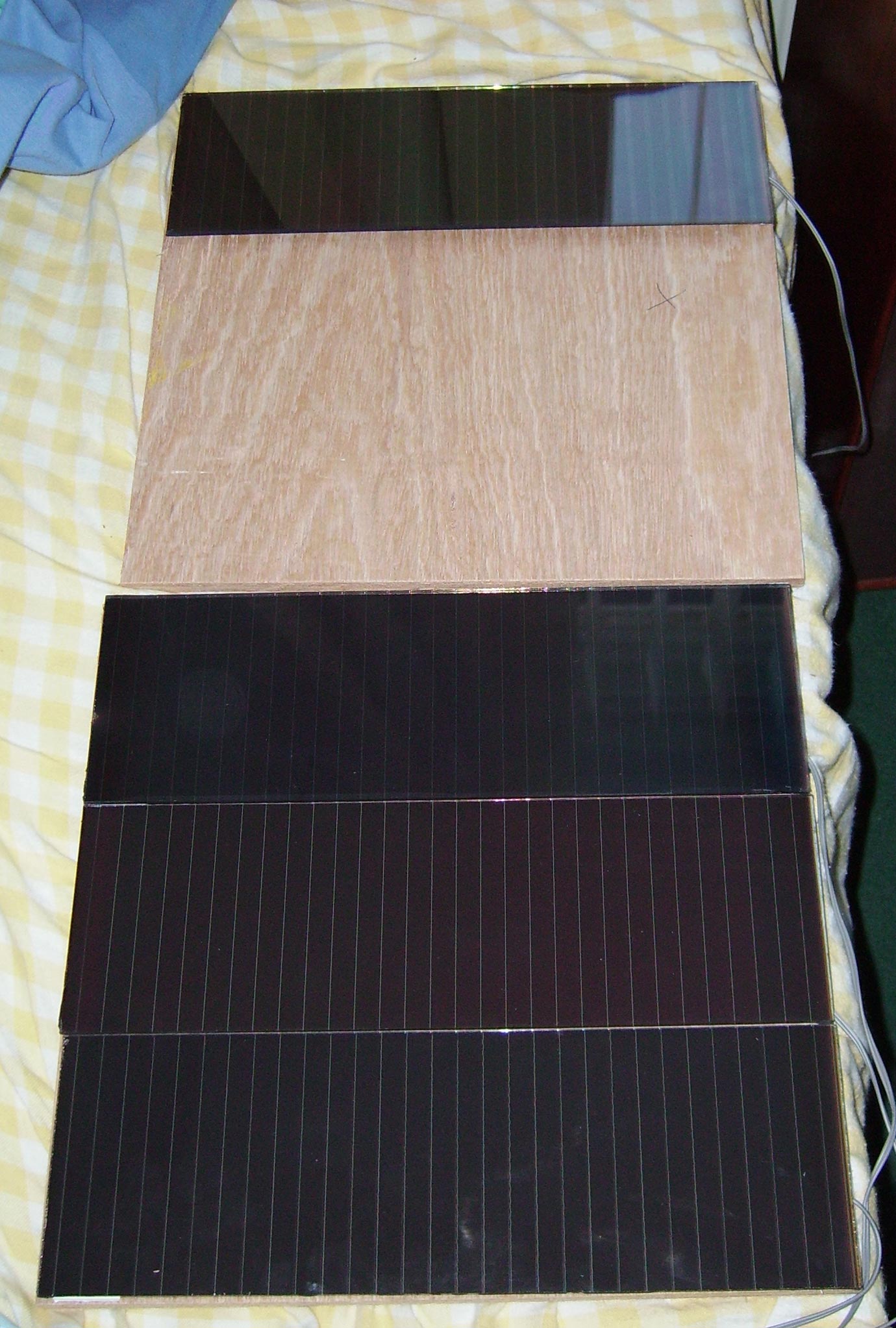
|
25th July:
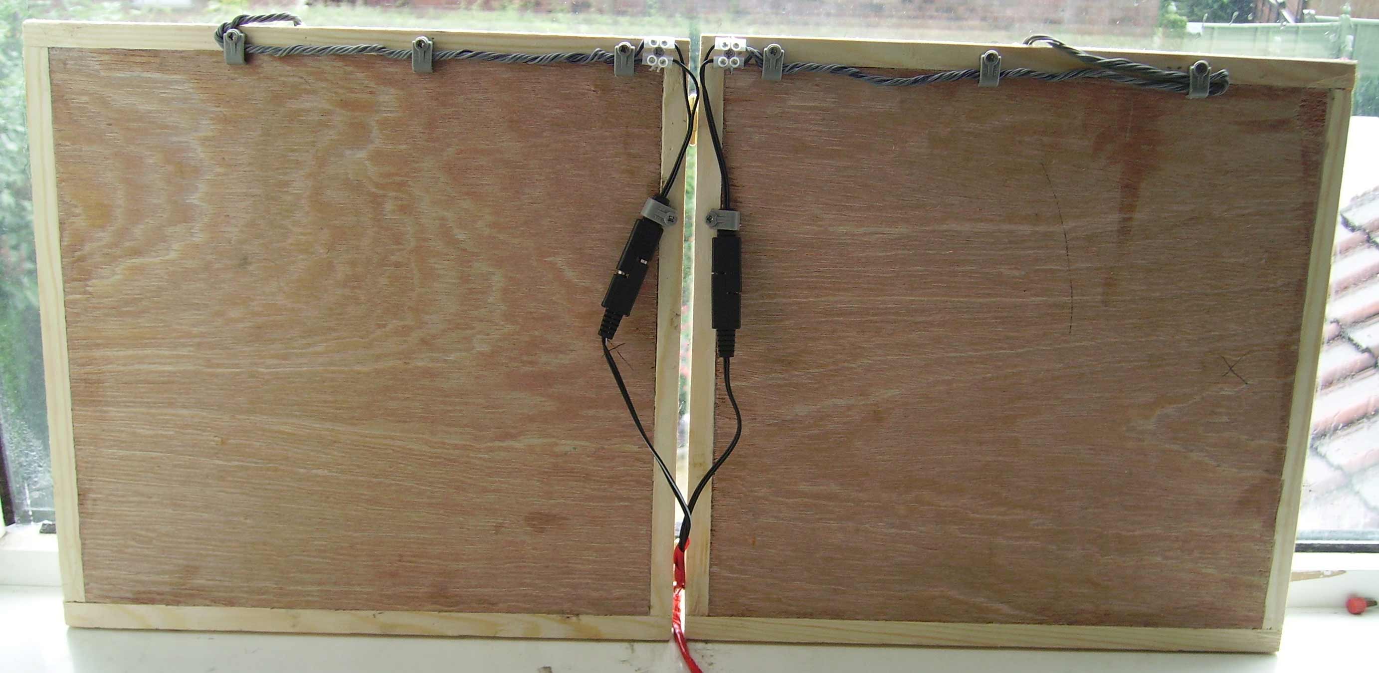
| A few days ago I got the panels mounted and today I got the sides put on. This will help to protect the panels when I make it into a foldable briefcase type setup. Its still not finished as it is though. It still needs varnishing to protect it from the weather and it needs sanding off as well so make the edges smoother. I still have all the wires loose so I can mess with them when each panel is finished. For wiring im thinking of using the original connectors that came with them because they look very good for the project. Ill end up having a connection block on each panel and the original connectors on each. Ill then have the other end of the connector on the charge controller. Ill need four connectors in total. Two for the panels and two for the charge controller. Im going to need some small hinges so it will fold and unfold but Im not yet sure of what size Ill need. Ill have to do some measurements and then go to B&Q and see what they have. | 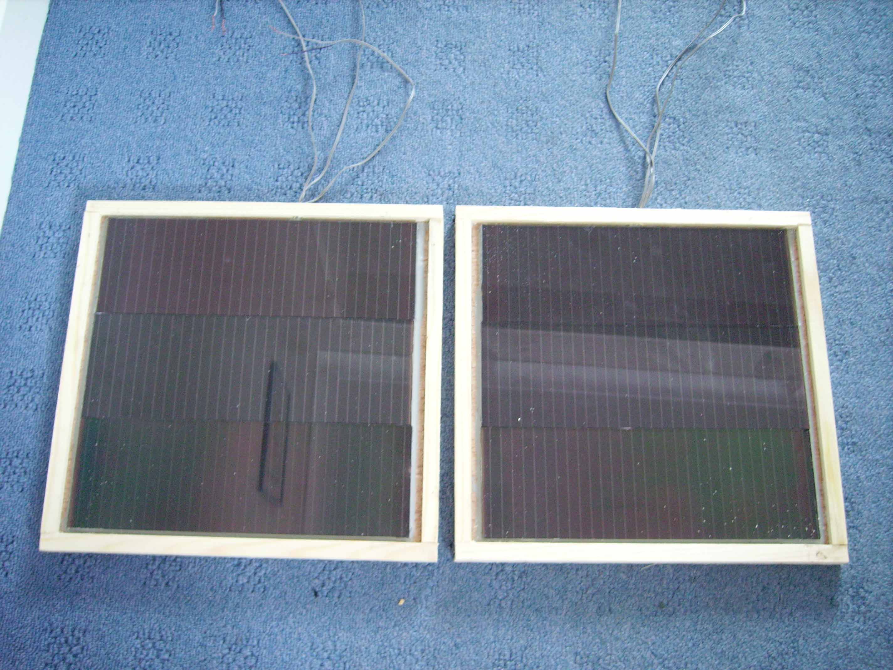
|
29th July:
I just did a quick test with both arrays and I got the following results:
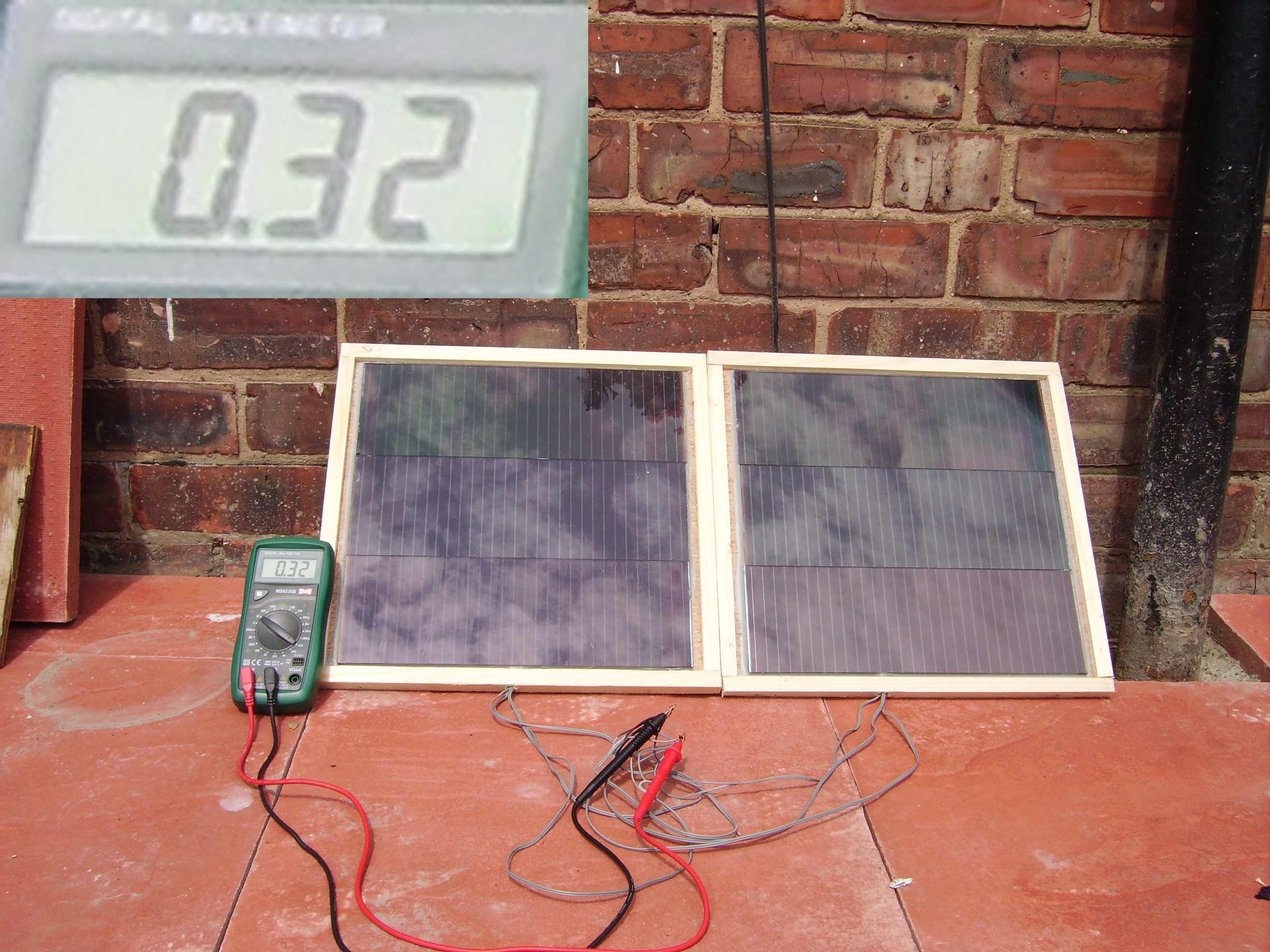
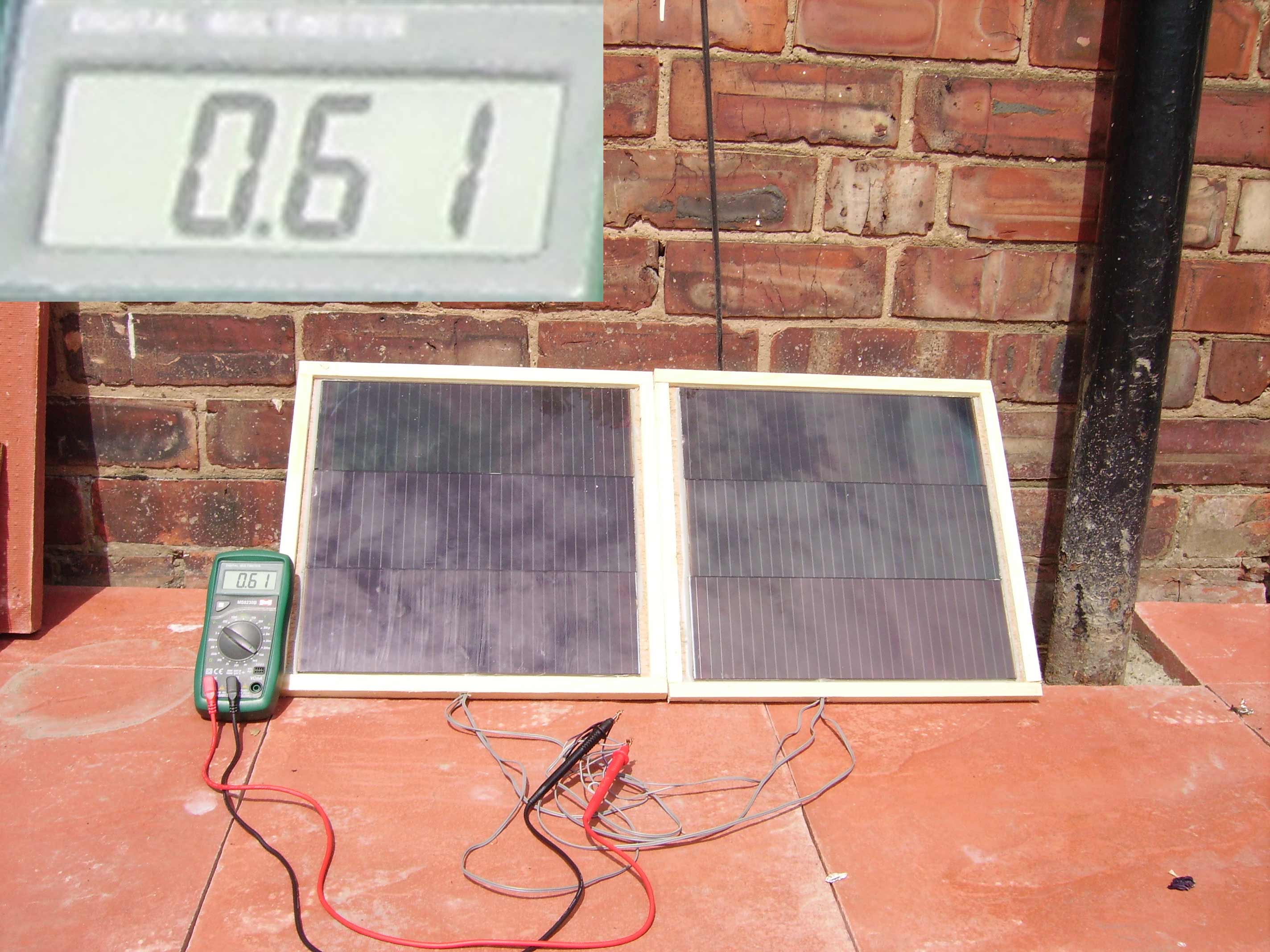
These results were far better than I expected. It was slightly overcast but when the sun managed to emerge from behind a cloud, I managed 0.61A! I calculated around 520mA when I tested each panel individually so this is a great acheivement.
Hopefully today and/or tomorrow I can begin finishing the arrays in terms of smoothing down the wood and giving it a lick of varnish. I also need some hinges and something (probably a piece of wood) to make a stand for it.
30th July:
Today I managed to plane the wood to so it was smooth and get some silicon sealant round the edges of the panel where there was a gap. Its almost finished now. All that is left is to paint it when the silicon goes off and then attatch the hinges which I got today, then wire up the two arrays. That is a job for tomorrow if I get chance.
After another current test today concluded at 0.6A short circuit, I concluded that is around 10.5w at 17.5v. I was very pleased considering its rated at 9w. It seems that calculation is incorrect. Im currently searching for the correct calculation!
UPDATE: OK, it seems I need to test the panels while connected to the battery. That means I need to flatten the battery to around 12.5v and then connect the panels to it, and test the current going through to the battery. Im only going to do this in 100% sunlight as I want the highest current reading as I can. This will give me the best idea as to how powerful the panels actually are.
1st August:
Yesterday I did the hinges and all the connections so I could use the panels and test them before I paint them. Unfortunately today its raining so I can't test the panels.
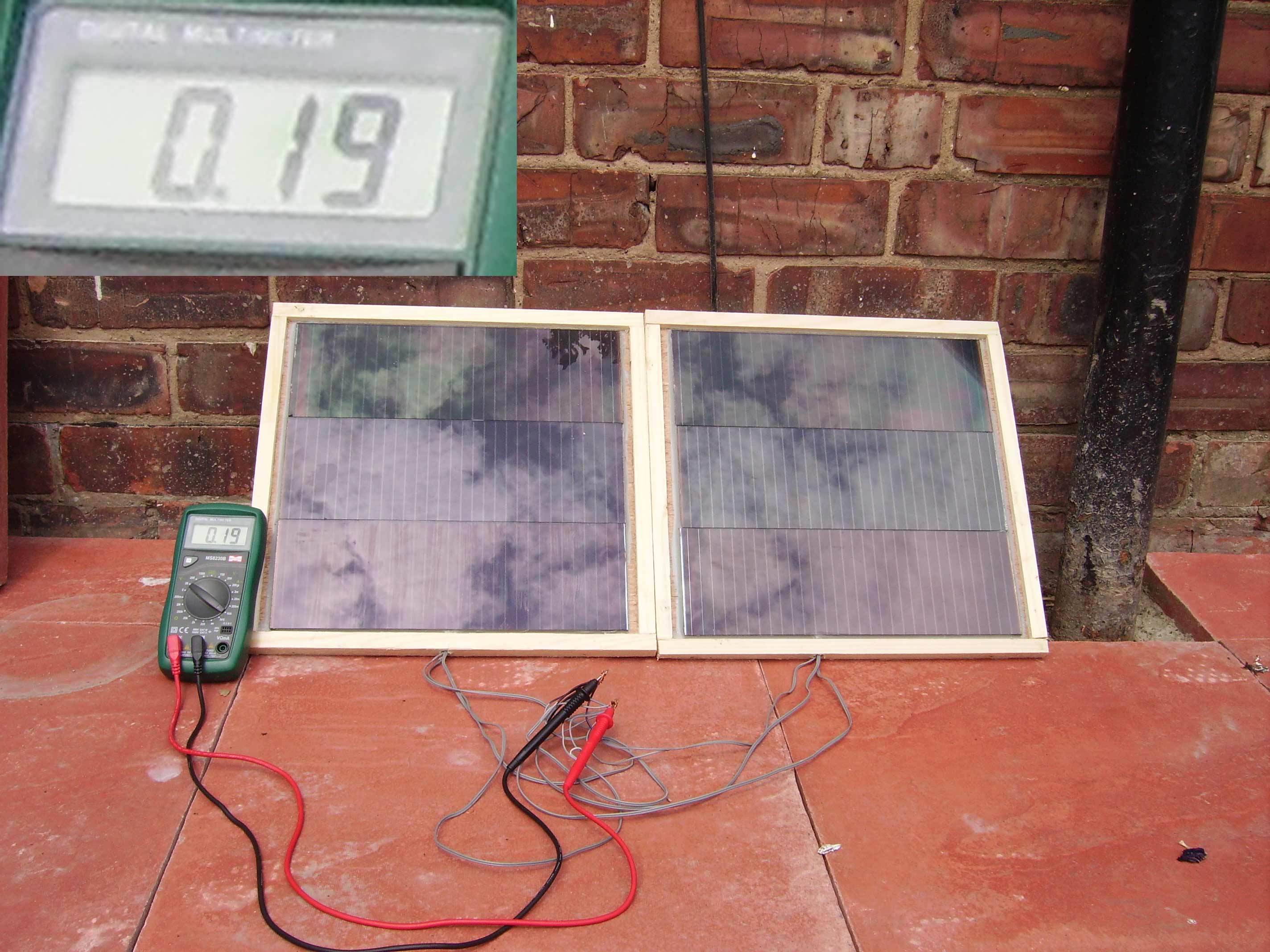
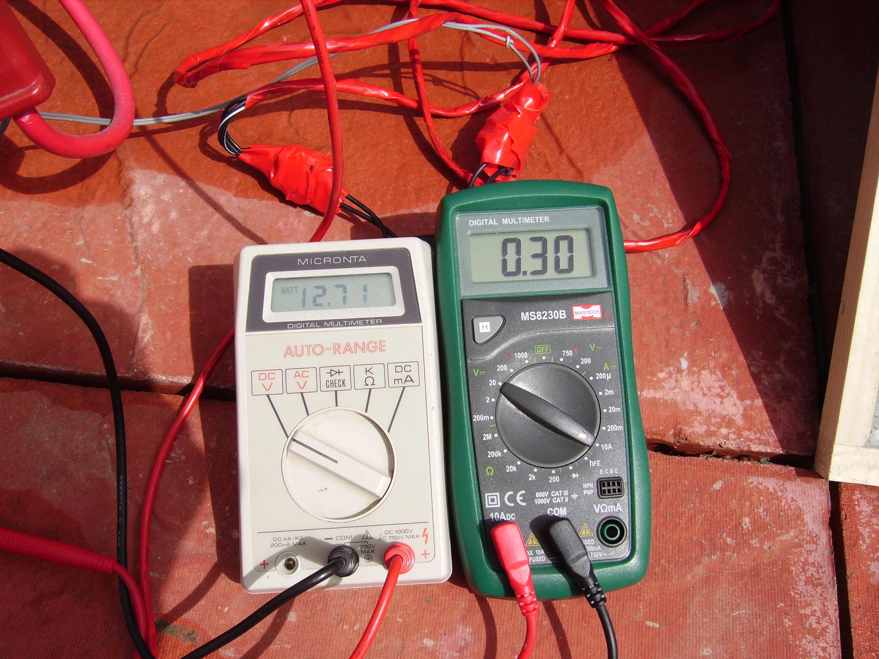
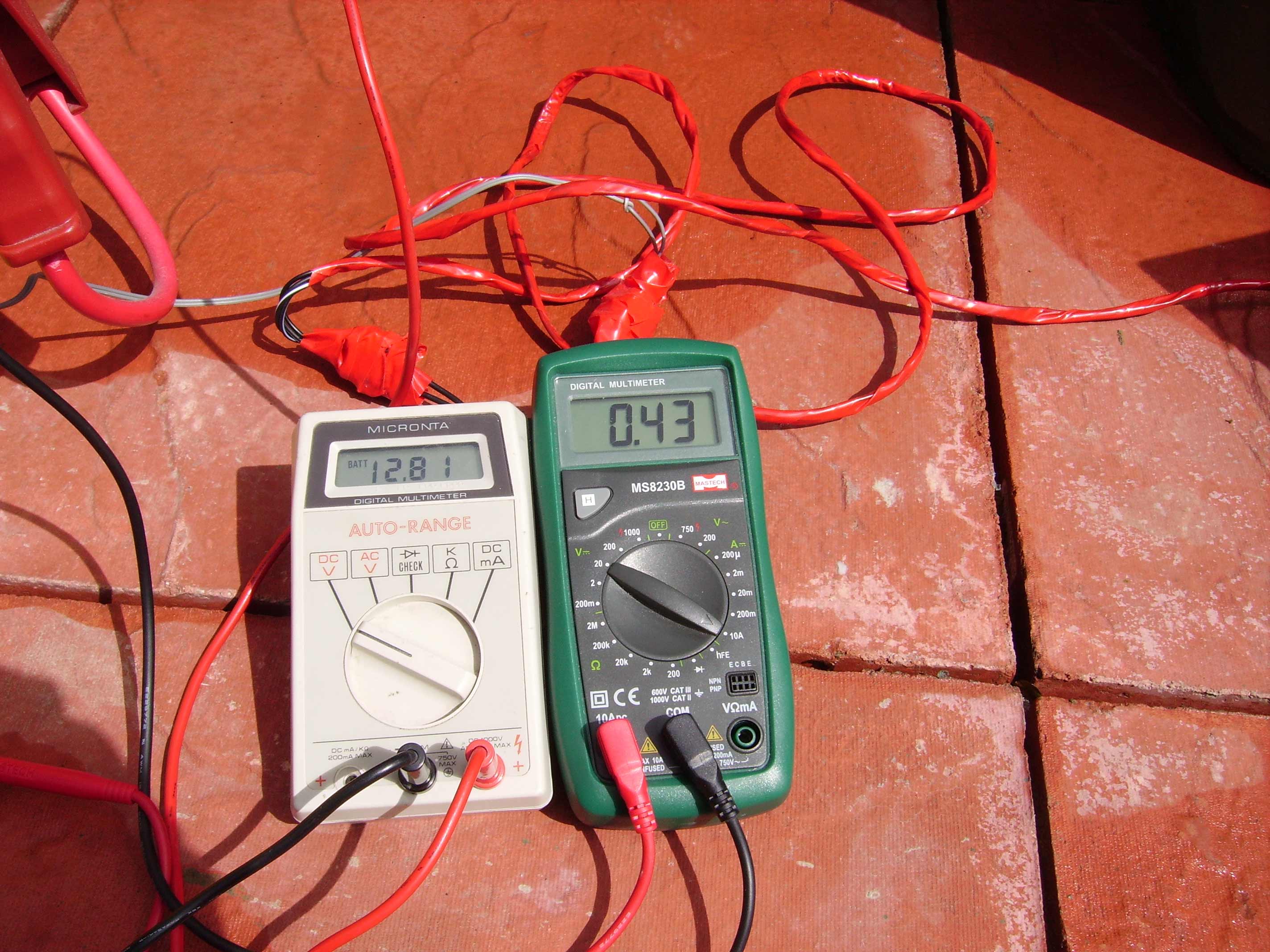
Later today:
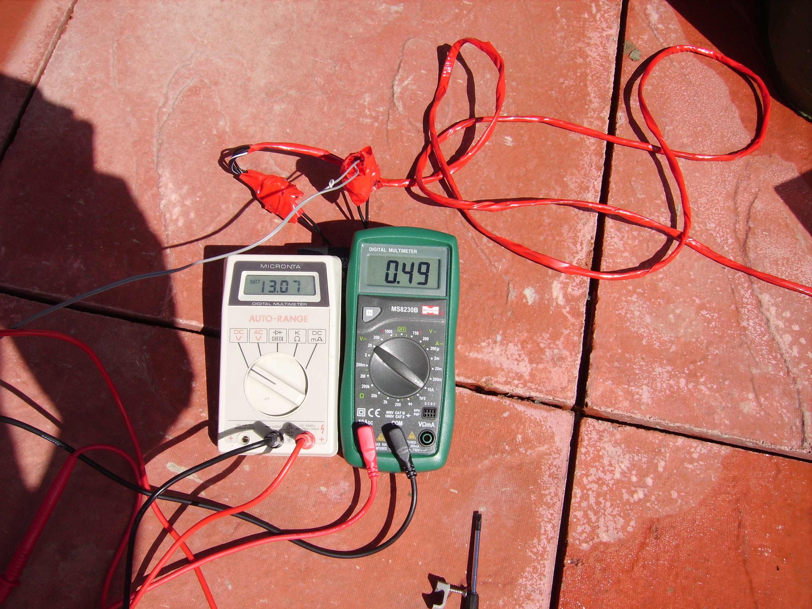
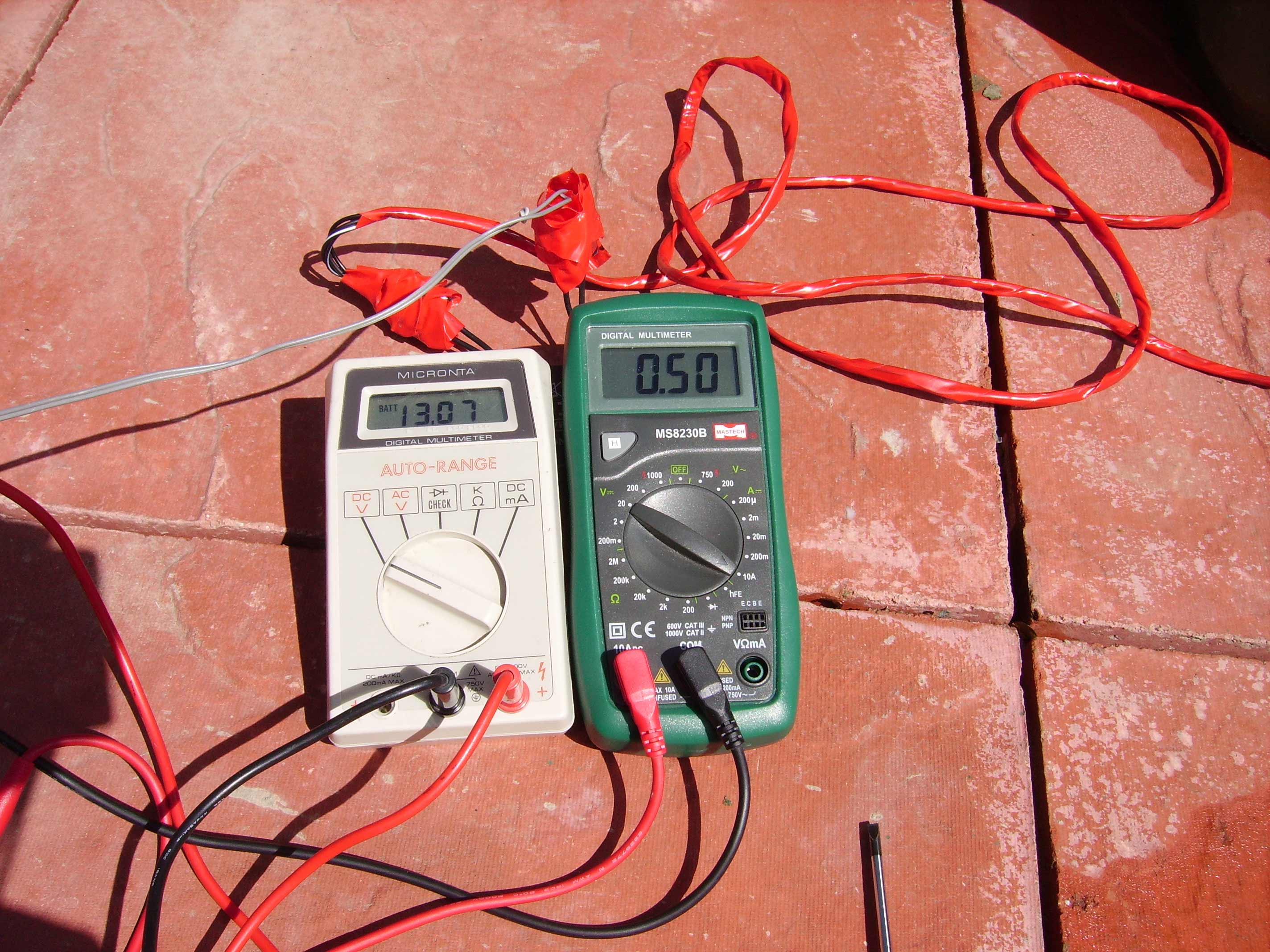
The sun managed to get out for 15 mins so I could do the tests. The results were quite good. The battery was at 12.50v when I began testing and finished at 13.07v!
13.07v * 0.51A = 6.53watts
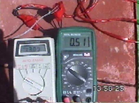
Unfortunately I didnt capture the 0.51A on camera as the batteries went flat but I did manage 0.50A. (later I found a 0.51A on the camcorder! (last of the 6 images))
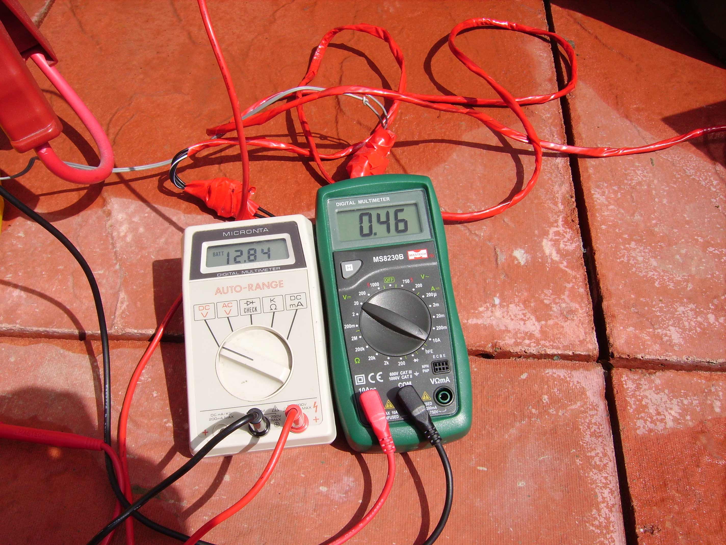
After a 10 minute "no charge" rest the battery levelled out at around 12.85v. I postponed the rest of the test because the rain started again.
6th August:
Finally I have finished the panels! Here is a picture of the panels mounted on the roof of my shed.
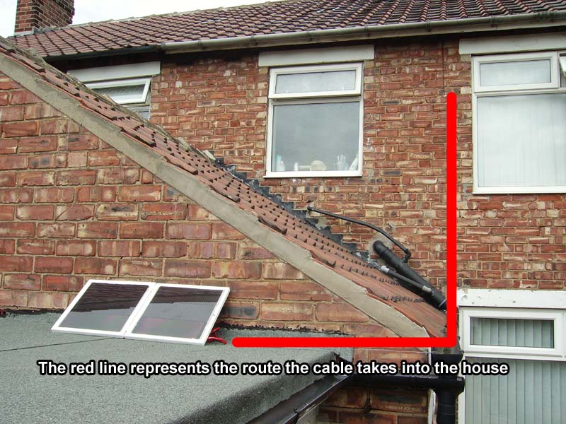
In this light they were giving out 160mA into my battery which isnt bad considering it is completely overcast.