
Arduino PWM Charge Controller
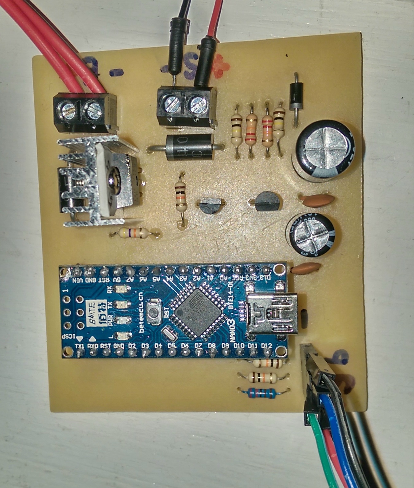
This week I finished my latest Arduino project which was my own PWM (pulse width modulation) solar charge controller. I made this primarily for the power box project as the charge controller in it at the moment is a very dumb one. When it hits a certain voltage it cuts off and doesn’t come back on until a lower voltage. This is useless when charging a battery properly so I decided to make my own that would use PWM. This means it always receives a “maintenance” charge.
Like most of my projects this one has been in the works for some time. It was only this week that I took it from prototype and onto the final production stage.
Main components:
– Arduino Nano board
– 5v Regulator (low quiescent current)
– IRF9520 MOSFET
– 2n3904 Transistor
– RGB LED
– 2x3A Diodes
– 1x1A Diode
– Several Resistors (2x 100k, 2x 22k, 3x 10k, 1x 4.7k, 1x 2.2k)
– 2x Electrolytic Capacitors (minimum 16v, ~470uF)
– 2x Ceramic ~100nF Capacitors
Features/Specs:
– 255 step PWM power control
– Solar panel and battery voltage aware
– Over/undershoot protection (software)
– Over-voltage (15.0v) protection (software)
– Automatic Bulk (14.5v) and float (13.5v) modes
– RGB status LED
– Re-programmable with updated firmware
– 9mA power consumption
I decided to use a pre-built nano board because it minimises wastage if the project does not work or I decide not to continue with it. Those components tend to cost the most and it means I can re-use them and replace them if needed.
I carefully chose the 5v regulator to minimise power use. A standard LM7805 regulator uses 5mA even when not being put under any load. 5mA in this sort of project is quite high and it doesn’t cost much to put in a low quiescent current regulator in its place. This combined with a reduction of the standard 16MHz clock speed to 2MHz using a clock pre-scalar, I have got the power usage down from 40mA to 9mA. I suspect some of the circuitry on the Nano board is using some power (such as the 3.3v regulator) that I couldn’t avoid, otherwise 2MHz should be down in the 4-5mA range. Still, compared to my other charge controller which uses 26mA, this is very good and I’m more than happy with it. In addition to this, I am planning a “firmware” update which further reduces power consumption at night by allowing the CPU to sleep further when there is no incoming power to control. If the Arduino was on its own I could get the power usage down to only microamps but with the additional components I’m not sure yet how low it will go.
The code is of course what really powers this project. Nearly all code was written from scratch by myself (some was copied and tweaked from other projects) and takes into account the need to charge at a higher voltage first (bulk) then change to a lower voltage to float, and also over/undershoot of the voltage target. This means that it is as stable as I can make it with the only limitations being the limited 10bit ADC and 8bit PWM on the Arduino (this makes the voltage readings and control less accurate).
LED status:
Red = Bulk charging (14.5v)
Green = Float charging (13.5v)
Blue = Low or no solar input/Night mode
White = Powering up
Resources:
If you like this project you can download the resources below, although some of the component specs are not listed and it comes as-is without any help, instructions or warranty of any kind.
Version 1.0: Original release.
Download Circuit Wizard Template & Arduino Code (9KB)
Version 1.1: Includes sleep code for night time power savings.
Download Circuit Wizard Template & Arduino Code (12KB)
This project still has to prove itself and I may change the code some more, but hopefully I will put it into good use shortly.