
Arduino PWM Charge Controller V3
This project has been a relatively long time in the making, but here it is, the next iteration of the controller.
Specifications
- 3x P-Channel FQP27P06 in parallel for lower total resistance
- Low quiescent current 5v regulator for minimal power consumption
- 2x40A diodes in parallel for lower total resistance
- 30A hall effect current sensor
- Modular design to enable upgrading of the power board
- Current design limit 10A (may be capable of more but untested)
- Power consumption: 7mA (no solar input) to 35mA
Features
- Voltage reading (accurate to +/- 0.02v) for battery and solar panel
- Translates into a percentage reading with hysteresis
- Software over-voltage protection
- Current reading (accurate to +/- 0.1A)
- Continuous polling
- Records power flow in Ah and Wh
- 2 sets of records for running and total records
- Readings stored in EEPROM in case of CPU reset
- 255 step PWM controlled output
- Adjusted up to 700 times per second
- 3 charging modes
- Bulk
- Absorb
- Float
- Night detection to lower power consumption
- Lower CPU frequency
- Turns off current sensor
- Lowers backlight brightness
- Button for additional functions
- Changes screens
- Resets power flow totals
- Over temperature cut-off
- Protects diodes and MOSFETs from damage
- Override available in case of temperature probe failure
- Firmware upgradable
- RGB status LED
- Red = Bulk
- Orange = Absorb
- Green = Float
- Blue = Night / No solar input
- White = Power up sequence
- Multiple screens available
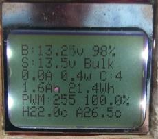
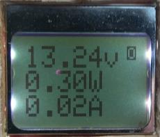
- Full information screen
- Volts, Watts, Amps
- Volts, Wh, Ah
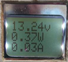
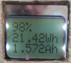
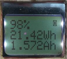
- Rotating screen
- Volts, Watts, Amps
- Battery %, Wh, Ah
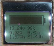
- Graphical screen
- Battery bar
- Volts
- Battery %
- Amps
- Watts
- Ah
- Wh
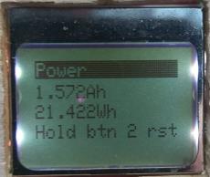
- Power
- Hold button on this screen to reset values
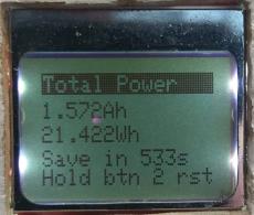
- Total Power
- Hold button on this screen to reset values
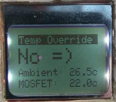
- Temperature override
- Hold button on this screen to enable/disable temperature override
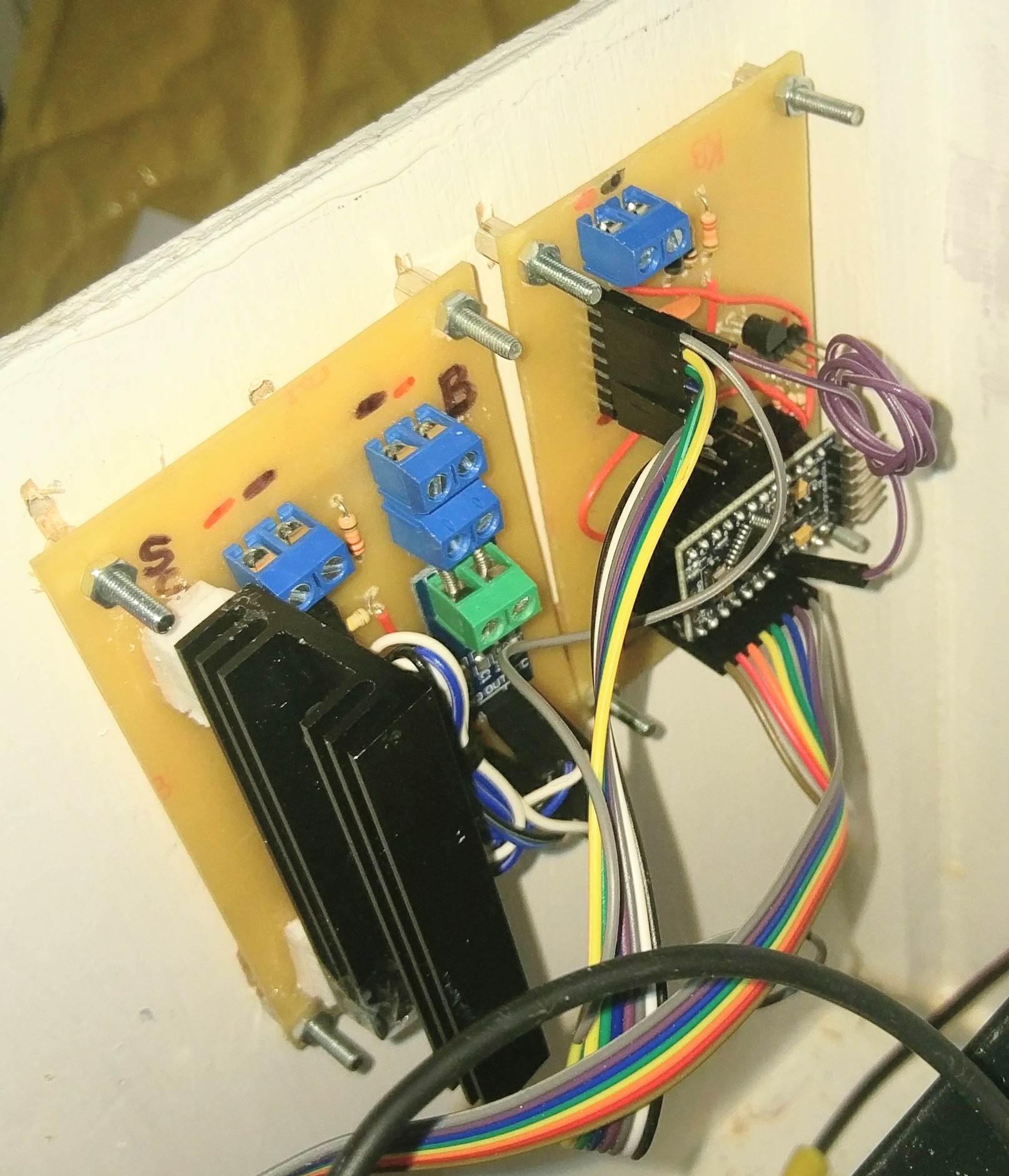
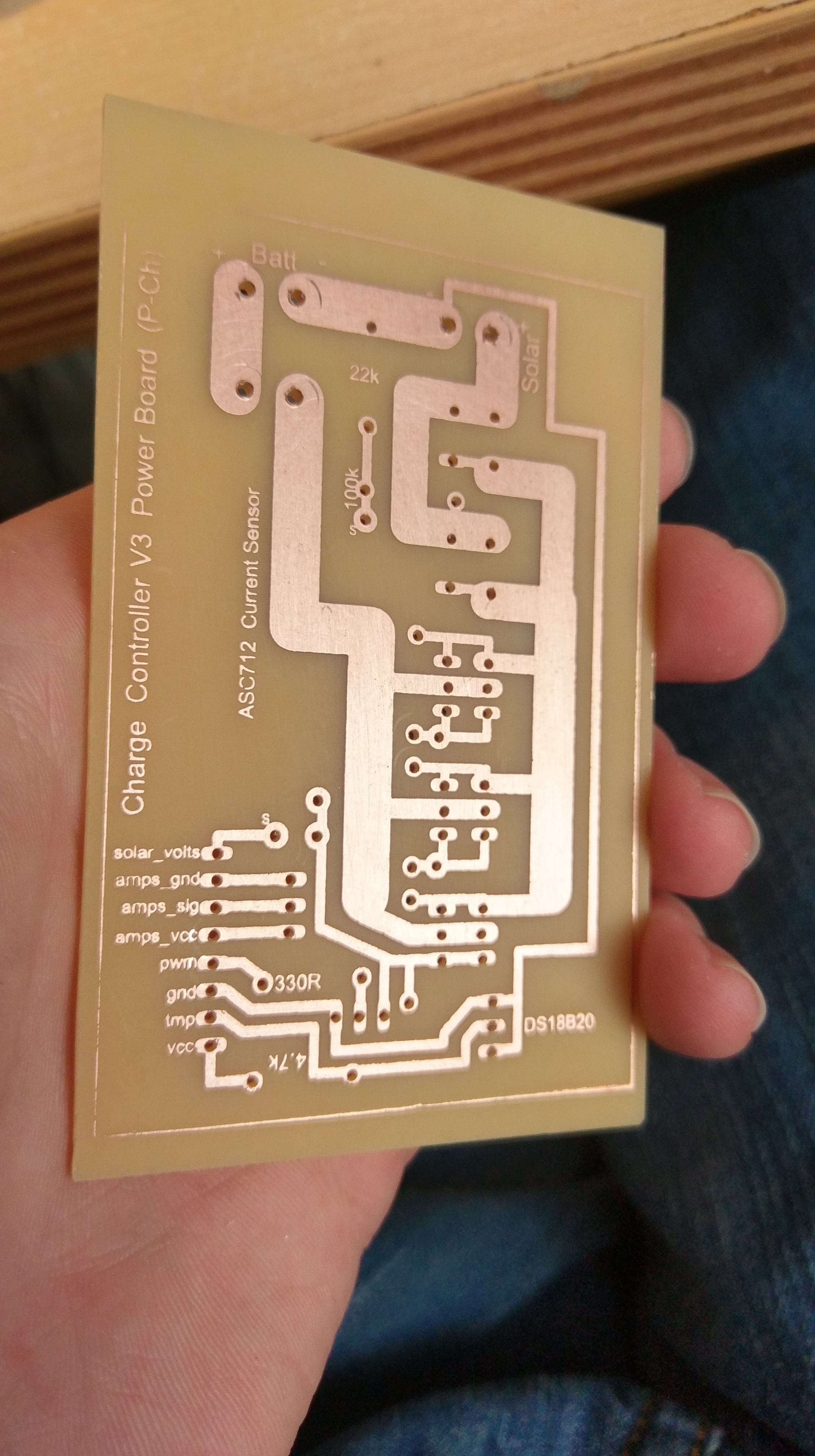
Gallery
Flaws in the design
As with anything I make, not everything always goes according to plan. There is one flaw with the project that I found whilst I was writing the software. The ambient temperature probe picks up heat from the voltage regulator through the copper tracks, making it slightly inaccurate (it reads high). If I had to re-make the control board I would move it further away from the regulator and put a large copper pad around it to take away any heat that is transmitted.
Challenges
There were several challenges in this version of the controller.
Initially I wanted to use N-Channel MOSFETs because they have lower resistance and are easier to drive. However I quickly found that this wouldn’t work without some complex drive circuitry. For loads N-Channel is easy, but for power shunting from a solar panel it requires complex drive circuitry in the form of a charge pump or a MOSFET driver. Needless to say I wasn’t prepared for that set back so I decided to go with P-Channel once again.
Another challenge was the software. In order to get the best possible voltage control the software has to run as quickly as possible. This means making it as efficient as possible because of the limited CPU speed. I quickly found that using timers was the best way to get around this. The main control loop runs unrestricted but non-essential code runs less frequently. The screen updates every 500ms, and everything else runs every 1 second.
Circuit Layout
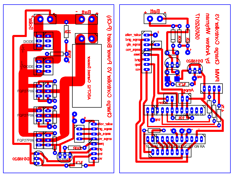
I realise that many of the components are not labelled, sorry!
Code
Version_3.00 (12KB) – 04/06/2017