
New Power Box Mock-up
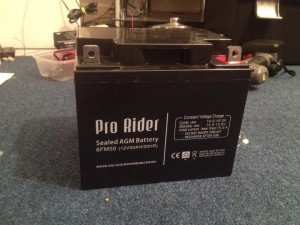
The new 50Ah SLA battery
If you’re familiar with my blog then you’ve probably read this post about my power box that I built for camping. It’s served it’s purpose well over the last couple of years, but recently I discovered that the battery was starting to get weak. The 90ah SLA battery inside is about 6 years old now and when tested I found it only holds 35% of it’s original capacity. Considering it’s size, it was time to replace it with a new one.
When going over ideas for the new box, I realised that 90Ah was probably a bit on the large side. Now that I have the 10W solar panel to go with it, the box didn’t really discharge much last year when we were camping as the solar was keeping it topped up. Therefore I decided to instead get a smaller battery as a replacement. What I settled on was a 50Ah SLA battery instead (see picture 1).
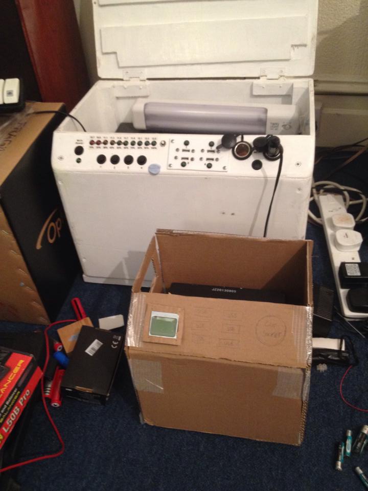
Old box vs new box mock-up
Now because this battery is much smaller than the 90Ah battery, I decided a new box was in order as well as the original is already way over-sized for what it’s containing. I found that the easiest way to design it was to make a cardboard mock-up so I could check everything fits (see picture 2). As you can see the size difference is huge, there is at least a 40% reduction. I decided to make it more compact than the first one. The original box was over-sized so that I could fit in various things like the solar panel (pure luck this fitted), lights, chargers, etc. This time I won’t be doing that purely for space reasons. There was a lot of wasted space inside it.
I’m able to make the front panel smaller on this new box too because I’m introducing the Arduino powered voltmeter (and temperature meter). This takes over the function of the LED bar on the old one. In fact, let me do a breakdown of the features this new box will have:
– Arduino powered voltmeter and temperature display (backlit)
– 6x 1-3A USB ports (current rating undecided at the moment)
– 2x cigarette sockets
– 5A solar charge controller + socket for the solar panel
Possible additions:
– 1x 600w power inverter (undecided if I will include this)
– Outside access to the +/- terminals for jump-starting/charging
One of the biggest concerns I have at the moment is being able to fit the USB power supplies onto a single board. It will depend on whether I use 1A or 3A power supplies. The 1A power supplies have proven very reliable and all of them still work great. The 3A power supplies are essentially exactly the same, except it’s an LM2576 (3A) instead of LM2575 (1A). The biggest problem is heat. At 3A they generate a LOT of heat, 2A is the safest I can get away with using the same heatsink. However there is no way to limit them to 2A so I will be taking a risk by using the 3A supplies and splitting between 2 ports. Phones typically will only use 1A or less anyway so there shouldn’t be much of a problem. Finding one big heatsink for them all would be a nice option but heatsinks are hard to find in the right shape and size. So I am caught between which one to use. I will likely go 3A for simplicity and hope for the best (I.E. hope they don’t overheat), otherwise I need 6 supplies instead of 3. Both circuits use the same footprint regardless (minus a bigger heatsink if chosen).
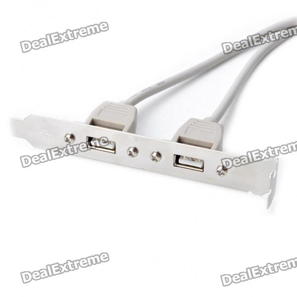
The panel mount USB ports will be mounted on the front on the aluminium plate they come on for ease of mounting. I learned last time that they’re hard to mount so I’ll save the problems this time and just use the plate it comes on, plus it will keep them nice and steady and hopefully neat too. The header sockets it comes with also makes it nice to plug into my board if I properly design it to use the header pins. I’m thinking about neatness here as the last one was terrible. Considering I intend to take this across the border into France when I go to Le Mans it can’t look like an explosive device of any kind otherwise I might be questioned! Neatness also minimises risk of short circuits etc too.
For now this is about all I can add. I will be getting the plywood and paint etc, at some point in the next week or two after I get paid. Then it should take me a weekend or two to build the box after I make the final measurements, and then a week to do the electronics. After that it should be good to go! This needs completing ideally before I go to Silverstone but the old one will still be there if it’s not, otherwise it needs doing before Le Mans so I have plenty of time (just over 2 months).
I’ll post some more updates here when I do more work on it, including the schematics for the Arduino display if I remember.