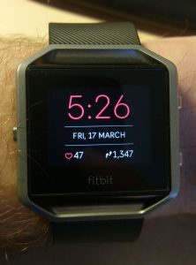
A year with the Fitbit Blaze – How it helped me lose weight

Posted by under Electronics, on 1 April 2018 @ 7:12pm.

I’ve had my Fitbit Blaze for a year now so I thought I’d just do a quick post about how it’s helped me lose weight and keep in shape.

Fitbit Blaze

After a health scare earlier in the year it kicked me into gear on getting myself into better shape. Not only that but also eating healthier was on the agenda. One of the things I wanted to try was calorie counting with a calorie deficit of 500 calories per day to make sure what I was eating didn’t exceed what I was burning, as well as deficit so I was able to lose weight. Boy was I surprised! My typical intake was always over what I was using in my typical day at the time.

My diet back then consisted of anything you could put in the freezer and cook in the oven for 25 minutes. Those sorts of things tend to be high in calories just in general, and one of the biggest offenders were chips and pizza. Any type of carbohydrates are huge on calories, so it was definitely time to cut back on those.

The other offenders were chocolate and biscuits, or chocolate biscuits if you want it twice as bad! I used to eat a lot of them as a snack after work and before my dinner. Those are also off the list.

To change what I was eating I initially tried to eat just healthy food – potatoes, vegetables and protein (chicken for example). That went well for a few weeks but I was finding it boring. The taste of the food was pretty bland and I have no culinary skills to ‘spice’ things up a bit. With that in mind, I kept eating healthy food but also mixed it up a little during the week. I saw no need to eat healthy food every single day, but as long as I was combining it with things that I liked too it should work out OK. Cutting back on portion sizes helped me with this a lot.

In the end, I only calorie counted for about 3-4 months, and then I stopped. By that point I was easily able to judge the calories in what I was eating so I didn’t need to track them anymore.

Along with the change in diet I began walking during my lunch break in work as many times a week as I could. I typically walked for about 45 minutes which was about 2-2.5 miles. That racks up about 300-400 calories burned each day. I still do this now a year later and it’s become a good habit.

My weight loss goal after just 3-4 months was about 75% complete. I was pretty happy with that as I hadn’t been close to that weight for around 6-7 years. I continued anyway and I still do today, but now that my weight is where I want it I’m able to eat more calories to keep my weight stable, so that means I can eat more of the things I like again like chocolate! I still eat healthily at least 2-3 times a week, semi-healthily 1-2 times a week and the weekend is free reign on whatever I like.

I still wear the Fitbit Blaze today as a regular smart watch. The fitness side of it is now just a bonus. That said, I think I’d still buy another Fitbit if this one broke because it’s been a very good device. I always get 3-4 days battery life, sometimes 5 days. It’s never given me any less so it’s not a hassle to charge it. It also gives a good 24 hours notice on when it needs a recharge which is awesome considering some smart watches can’t even give you a day in the first place!

I’d say it was a very good £130 well spent.


Home automation using Alexa and Hive

Posted by under Electronics, on 20 January 2018 @ 3:10pm.

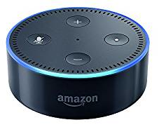
This is something I’ve wanted to do for a while, and for Christmas I was fortunate enough to get an Amazon Echo Dot and some smart Hive bulbs.

There are different combinations of systems out there including Google Home and Google Assistant to compete with Alexa, and Philips Hue to compete with Hive, and they all have their pros and cons (something I’m realising now). Alexa does a very good job at serving my needs so far, and Google Assistant which I can use on my phone supplements that.

At the moment I am able to control 2 lights in my flat using Alexa, an Android app and Google Assistant. I mostly use them on a timed schedule to turn on and off at set times, but I do have the option of controlling via Alexa and Google Assistant as well. It’s surprising how often you may want to turn your light on and off but never realise that you do it. You take it for granted when you flick the switch on the wall.

Something I find nice with the Hive bulbs is that you can dim them from 5-100% in 10% steps (5% for the first step). This is nice if you want to leave a light on overnight or late evening but dimmer so that you don’t hurt your eyes if you need to get up for the toilet. Personally I have my hallway light dim at 11pm to 50% and then again at midnight to 5% until 1am when it turns off. It also helps me to keep track of the time.

The bulbs don’t dim gradually, they just jump straight to that setting. Philips Hue bulbs on the other hand apparently don’t do this, but they’re also much more expensive (about twice the price). So you get what you pay for in that respect.

You can also get RGBW bulbs; these are multi colour with a separate white so that you get a true white not a mixed colour white. I don’t have any of those yet but I have seen examples where they can give some great results to the ambiance of the room. The cost of those is also quite high!

So besides bulbs what else can you control? Well, anything that can be internet connected in theory. That could be a toaster, microwave, kettle, washing machine, a roomba vacuum cleaner, anything really. Hive do some other sensors such as door and window sensors, cameras, motion sensors and moisture detectors which would be useful to those that are very security conscious. I was considering a door sensor in the future but not at the prices they are currently sold for. They’re just not worth that kind of money (£25+). A white only bulb alone is £16 from Hive at the moment.

Hopefully in time the prices will drop or I can get some good deals when they’re on offer.


Arduino PWM Charge Controller V3

Posted by under Electronics, on 4 June 2017 @ 12:49pm.

This project has been a relatively long time in the making, but here it is, the next iteration of the controller.

Specifications

  • 3x P-Channel FQP27P06 in parallel for lower total resistance
  • Low quiescent current 5v regulator for minimal power consumption
  • 2x40A diodes in parallel for lower total resistance
  • 30A hall effect current sensor
  • Modular design to enable upgrading of the power board
  • Current design limit 10A (may be capable of more but untested)
  • Power consumption: 7mA (no solar input) to 35mA

Features

  • Voltage reading (accurate to +/- 0.02v) for battery and solar panel
    • Translates into a percentage reading with hysteresis
    • Software over-voltage protection
  • Current reading (accurate to +/- 0.1A)
    • Continuous polling
    • Records power flow in Ah and Wh
    • 2 sets of records for running and total records
    • Readings stored in EEPROM in case of CPU reset
  • 255 step PWM controlled output
    • Adjusted up to 700 times per second
  • 3 charging modes
    • Bulk
    • Absorb
    • Float
  • Night detection to lower power consumption
    • Lower CPU frequency
    • Turns off current sensor
    • Lowers backlight brightness
  • Button for additional functions
    • Changes screens
    • Resets power flow totals
  • Over temperature cut-off
    • Protects diodes and MOSFETs from damage
    • Override available in case of temperature probe failure
  • Firmware upgradable
  • RGB status LED
    • Red = Bulk
    • Orange = Absorb
    • Green = Float
    • Blue = Night / No solar input
    • White = Power up sequence
  • Multiple screens available
    • Full information screen
    • Volts, Watts, Amps
    • Volts, Wh, Ah
    • Rotating screen
      • Volts, Watts, Amps
      • Battery %, Wh, Ah
    • Graphical screen
      • Battery bar
      • Volts
      • Battery %
      • Amps
      • Watts
      • Ah
      • Wh
    • Power
      • Hold button on this screen to reset values
    • Total Power
      • Hold button on this screen to reset values
    • Temperature override
      • Hold button on this screen to enable/disable temperature override

Gallery

Flaws in the design

As with anything I make, not everything always goes according to plan. There is one flaw with the project that I found whilst I was writing the software. The ambient temperature probe picks up heat from the voltage regulator through the copper tracks, making it slightly inaccurate (it reads high). If I had to re-make the control board I would move it further away from the regulator and put a large copper pad around it to take away any heat that is transmitted.

Challenges

There were several challenges in this version of the controller.

Initially I wanted to use N-Channel MOSFETs because they have lower resistance and are easier to drive. However I quickly found that this wouldn’t work without some complex drive circuitry. For loads N-Channel is easy, but for power shunting from a solar panel it requires complex drive circuitry in the form of a charge pump or a MOSFET driver. Needless to say I wasn’t prepared for that set back so I decided to go with P-Channel once again.

Another challenge was the software. In order to get the best possible voltage control the software has to run as quickly as possible. This means making it as efficient as possible because of the limited CPU speed. I quickly found that using timers was the best way to get around this. The main control loop runs unrestricted but non-essential code runs less frequently. The screen updates every 500ms, and everything else runs every 1 second.

Circuit Layout

I realise that many of the components are not labelled, sorry!

Code

Version_3.00 (12KB) – 04/06/2017


WEC 2016, Camping, Power Box

Posted by under Electronics, on 26 June 2016 @ 9:40pm.

This blog is going to cover a number of things on my mind given I haven’t written a blog for a while. It’ll probably be a mish mash of all three since they’re all related in some way, so here goes…

So far this year I’ve been to 3 FIA WEC events, the first 3 in the season as it happens. It started in here in the UK at Silverstone for the first round. The second round took us to Spa in Belgium, and the third to Le Mans in France. I feel privileged to be able to attend so many of these events because I enjoy them so much. I live in an ideal area of the world that gives me access to 4 events – the places listed above plus the Nürburgring event added a few years ago.

spa_francorchamps_2016

All 3 of these events have been their own personal missions in some way or another. Silverstone I’ve done lots of times, but Spa was my first time this year. I have to say it’s a very difficult trip. Why? Well we travel there, watch the race, and travel home all in the same day. That means we’re awake for about 36-48 hours with little if no time to sleep. We could quite easily stay somewhere if we wanted to but if you can do it in a day then why not? It saves money and avoids needing time off work too. It’s definitely not something I would do every other weekend though – once a year tops! It really does take it out of you.

Le Mans. Now we’re talking. This has been my primary holiday of the year for a couple of years now as it’s a great way to spend time with friends whilst camping and enjoying racing, and on top of that getting to photograph them too. Not many people can say that their holidays let them enjoy 4 of their favourite activities in one go.

This year felt a little different though as we were one person short for the majority of the holiday. One of our friends wasn’t able to get the time off work so he only came up for one night, the night the race was on. As soon as it was over he was on his way back home again. It definitely felt odd with him not being there. He almost wasn’t the only person who wasn’t able to go either. One of our other friends almost couldn’t go because his holiday was rejected last minute by his work. Thankfully he managed to sort it out 2 days before we were due to go! Talk about cutting it close… He won’t make the same mistake last year so he’s booking it as soon as he can!

power_box_june_2016

Now then, power box… I’m still planning upgrades to the power box because of what I’m about to talk about. I should add that it has been upgraded since my last post through the addition of 2 speakers and an amplifier in the front. We’ve wanted this ability for quite a while since music is something we all enjoy whilst camping, and speakers on mobile phones really don’t cut it. I got the speakers for free off a friend and the amplifier cost about £5 online. A little modification to attach it to the box and it was good to go. Definitely worth the effort.

We tried the speakers out for the first time properly at Le Mans, though we tried them in Silverstone successfully too. We kept it quiet though and because we weren’t near the track we couldn’t tell if the volume it was capable of would be enough to get over the top of the noise of the cars. We wanted this ability so we could put the radio broadcast through it. As it turns out, it was plenty loud enough for this at Le Mans.

camping_solar_2016

Power consumption is quite high from this amplifier, and you can tell it’s not very efficient because it gets quite hot. I did some initial tests before I put it in the box and it uses up to 2A depending on volume and the audio being played. That could very easily kill the power box in just 24 hours if uses loudly without solar input. This is something we found out during the week at Le Mans this year. Come Friday we were at an unbelievably low 20% (11.00v) charge with just a couple of phones charging. I quickly made sure everyone was aware and we only charged phones if it was absolutely needed. I had a full 22,400mAh power bank available for my phone so I was in no desperate need of it.

Oddly, by Sunday we had managed to reach full charge again. I don’t know how though since only 18Ah of power had been put into it (unless it’s not been reported correctly on the display, but my testing did show it was relatively accurate), and some of that had been used charging phones and running the tent LED light. With a 50Ah battery that surely doesn’t add up. But hey ho, it showed 100% again and 12.8v under load which is indicative of a full charge. The green LED came on near the end of Sunday as well which indicates it hit 14.5v for at least 2 hours, again indicating a full charge.

In any case, I think a new solar panel next year is going to be needed. With mobile phones sucking more power, and us plugging in more things than ever before (charging power banks, charging up our hand held walkie talkies, and more), power is being drained more excessively than it was 2 years ago.

folding_80w_solar_panel

I plan on buying an 80w folding solar panel. This will be 2.6x more solar power that we currently have (30w at present). That should almost certainly be enough. It may even be more than we need, which is good in any case. Taking a lead acid battery below 50% doesn’t do it any good, and nobody likes it when power is low and you have to restrict your usage.

In order to use the 80w solar panel though I will need a new charge controller as well as the existing one is only capable of working up to 3A (36w) without getting far too hot. I am designing a new one which can cope with about 10A (120w) as a minimum which should allow for the 80w panel upgrade plus a bit more in the future.

It’s going to be an interesting project as I’m planning on making it into a monitoring controller as well. It’ll measure power going in and out of the battery as well as incoming solar power so we can see power consumption. At the moment it only measures the incoming power and not how much we have used. Because of this I can’t see what our typical power usage is so I can tailor the solar power to our needs. If I had that I could properly size the right solar panel instead of guessing. I’ve already ordered a fair number of the components for this so I can start work on it as soon as they arrive in the coming weeks.

Anyway, that’s all I’ve got for now. Watch this space for the next version of the charge controller, and maybe even a new power box front panel too.


New DSLR Camera / Car Auxiliary Power Switcher Update

Posted by under Electronics, Photography, on 12 January 2016 @ 9:33pm.

After having my Nikon D3100 for a couple of years now and getting plenty of use out of it, I thought it was time to update to a newer camera. I mainly wanted one which would do better in low light conditions and had a higher resolution sensor. Other features would be a bonus. In the end I settled with the Nikon D5300. It looks pretty much the same as the D3100 but with a few additional features…

– 24MP sensor vs 14MP on the D3100
– Higher ISO settings available
– 1080p 60fps video capability
– Stereo sound recording
– A pop-out screen which can rotate 360° on one axis
– GPS location and Wifi (for a smartphone app)

It is also compatible with my existing accessories such as batteries and lenses which is great, as it means I don’t have to find replacements for those too which could have got very expensive. That means my existing 55-300mm lense works on it too.

I haven’t had time to do a lot of testing with it but that will come on my next trip to a race track no doubt! Watch this space…


In other news, my Car Auxiliary Power Switcher has been working flawlessly since I rewrote the software on it. It’s been running continuously (bar the few times the power cable got knocked) without crashing, and without false positive turning on and off of the output. Perfect!

I do notice every day when I get in the car though that the LED is flashing red which means that my battery voltage is under 12.4v. The battery isn’t old and isn’t neglected so I wonder if modern cars have a somewhat higher parasitic draw than older cars or systems stay active longer when the engine is turned off. My old car certainly never had it drop below 12.6v (usually stayed higher). I did double check the drain on the power switcher and it was 2mA, not enough to draw it down overnight (or in a week even). No bulbs have been left on either. Oh well, the engine starts just fine every day so I’m not too worried about it.

Next project is another solar charge controller I think, with an upgraded rating and possibly input and output current monitoring. Again, watch this space!


Car Auxiliary Power Switcher

Posted by under Electronics, on 9 November 2015 @ 8:55pm.

I’ve been using a dashcam for almost a year now and right from the beginning I knew that my cigarette socket was not switched with the key. I’ve been using a device made by my friend John to switch the power on and off automatically based on battery voltage. I finally got around to making my own so I thought I would document it.

Very simply all it does is monitor the battery voltage. When it goes above 13.1v after the engine is started, it switches on. When the engine is turned off and it goes below 13.1v it switches off after a short delay. Simple. It saves the hassle of remembering to plug it in and prevents your battery dying by forgetting to unplug it.


Specs:

  • 7v-15v input (circuit will work between 7-30v but output voltage will reflect input)
  • Arduino Nano (Atmega 328p) running at 256KHz (cpu-scalar from 16MHz)
  • 5v low quiescent current regulator for the Arduino
  • Red/green bi-colour status LED
  • N Channel MOSFET for switching (under the Arduino Nano board)
  • 100k / 22k voltage divider for voltage measurement
  • Can switch around 3A happily (MOSFET rated at 25A but does not have adequate cooling, wiring or PCB traces)
  • Typical 1.7mA power draw current (output off)


Features:

  • Turns the output on if input is above 13.1v
  • Turns output off when below input is below 13.1v after 8 second delay
  • If voltage goes above 13.1v before turning off the delay will reset and output will remain on
  • Steady red LED shows when voltage is below 13.1v and the output is about to turn off
  • Steady green LED shows when the output is on and voltage is above 13.1v
  • Flashing green LED shows when off to indicate >12.5v battery voltage
  • Flashing red LED shows when off to indicate <12.5v battery voltage
  • Voltage accuracy is around +/- 0.1v


Component List:

PCB:

  • 1x Arduino Nano 16MHz 5v
  • 1x 5v Regulator (Texas Instruments LP2950-50LPRE3)
  • 2x 100nF Ceramic Capacitors
  • 1x 1N4001 Diode
  • 1x 100k 1/4w resistor
  • 1x 22k 1/4w resistor
  • 1x 4.7k 1/4w resistor
  • 1x 470R 1/4w resistor
  • 1x 3mm bi-colour LED (red/green) (plus SIL socket strip if you wish)


Download:

Download the Circuit Wizard PCB and Source Code (8KB)


Arduino PWM Charge Controller Version 2

Posted by under Electronics, on 27 May 2015 @ 9:07pm.

A few weeks ago I finished the final version of my 2nd Arduino PWM Charge Controller. I have been working on this since October 2014 on and off when time has permitted. Knowing that I am going to be using the power box soon for camping, I thought it would be a good idea to finish it.

You can see the post I made about version 1 of the charge controller here.

So what’s new?

A lot is new on this version feature wise, so let me list them one by one…

– LCD Display
– Current Sensor
– Voltage Sense Input
– Temperature Sensor
– Lower Power Consumption

LCD Display

screen

I thought long and hard about whether I wanted to put an LCD on this project or not. Ultimately I decided yes because I would be replacing the entire module that runs the existing screen with a new board anyway, so why not combine them?

My biggest concern with this was power consumption. LCD displays are not always known for their low usage, however I was confident I would be able to make this work. I have a lot of experience using the small Nokia style displays which are 80×48 pixels. By all means it is not a large display but it is only monochrome and is LED backlit.

Using the screen on it’s own is less than 1mA when it is not being updated. I don’t know the exact figure, but its pretty negligible. With the LED backlight on, the power consumption depends on the brightness at which you run the LED’s. For this project I run it at 2 different levels depending on whether it is daytime or nighttime.

Daytime gets a higher brightness to combat ambient light a little more easily, whereas nighttime gets a lower brightness as there is little ambient light to worry about.

Current Sensor

The current sensor (ACS712 based) is not required as it is there only as a visual reference (but I could code something into the firmware to make it calculate total power if I wanted to). All this does is show the current power flow from the solar panels to the battery.

Voltage Sense Input

I had issues with voltage sensing on the first version of the charge controller when large currents were passing through the board and the cabling. So on this version I have made an (optional) voltage sense input so that you can run a 3 wire setup. This should reduce any issues with voltage sensing. So far I have not noticed any problem not using it on my own setup, but the option exists should it ever be needed on longer cable runs for example.

Temperature Sensor

Using a DS18B20 DALLAS temperature probe I have put the temperature inside the power box onto the display. Although it is not currently implemented in the firmware, it would be possible to have charge voltage temperature compensation built into the programming.

Lower Power Consumption

The biggest win from re-making this charge controller is that I was able to focus more on power consumption as a major factor. From the beginning I was trying to get it as low as possible. To do this I had to be careful on not only the components I used, but also on the programming and how long some components were left active.

For example:

During the day, the LCD LED backlight runs at a higher brightness, pulling around 3-4mA. At night, the LED is dimmed to reduce power consumption.

The current sensor is active for just a very short fraction of time every second, just long enough to get a reading. The sensor uses 10mA when active, so this was definitely necessary. At night it does not get probed for a reading.

The CPU frequency remains at 2MHz at all times, except when probing the temperature probe in which it returns to 16MHz for less than 1 second. The temperature only gets updated once every 60 seconds during the day and every 4 minutes at night.

The RGB LED showing the status at a quick glance uses a very low PWM output of around 5% duty. As a result the power consumption is very low, though I do not remember the exact amount of current. By not using PWM or using 100% PWM, the LED is unnecessarily bright and that just wastes power. At night, the LED flashes blue every time the CPU wakes up (4 second intervals) just to signal it is still alive and aware it is night time.

Total power consumption when the CPU is in sleep is just 2mA. That’s 3mA lower than the old charge controller when it was in sleep.

Images

Specs

– 255 step PWM power control
– Solar panel and battery voltage aware
– Over/undershoot protection (software)
– Over-voltage (15.0v) protection (software)
– Automatic Bulk (14.5v) and float (13.5v) modes
– Solar panel to battery current display
– Temperature display
– RGB status LED
– LCD backlit display showing battery voltage, solar panel voltage, charge mode, current, watts, temperature and PWM %
– Voltage sense input
– Re-programmable with updated firmware
– 2mA at night, 7mA (15mA peak) during the day power consumption

Circuit Wizard Layout and Arduino Sketch

Download (14KB)

Apologies that there are no components listed for you to make this yourself. I do not have it to hand at the moment but I will update it here if I remember in the future.


Feeling a bit neglected… Not me, the blog!

Posted by under Electronics, Life, on 9 January 2015 @ 9:03pm.

It’s been a while since my last post – I’ve neglected the blog for the first time since I started it a few years ago. I’ve had plenty of things going on but most of it isn’t worth talking about. That said, I have a few projects on the go and have bought a few things since then.

For Christmas, a friend bought me a dashcam. One of the functions of it is that it powers up and starts recording on its own when you start the car. Unfortunately it only does this if your cigarette lighter socket is turned on and off with the key. Annoyingly, mine isn’t and it’s permanent live. When discussing with a friend months ago we came up with the idea of making something that would turn it on and off based on battery voltage, so he went ahead and made one. It works great, but now I’m in need of the same thing so I’m making my own variation too. I’ll probably make a full post about it when it’s done, I’m just waiting for a few parts to complete it such as a project box and an Arduino Nano chip to run it.

My second version of the PWM charge controller is going to be built at some point too. I realised how much power the USB version of the Arduino Nano was really using compared to how low I could get it, so I’m building another version to replace it with a non-USB Nano board. That way I can reduce the power consumption to 0.5mA when asleep during the night instead of the 4mA or so that it uses now. That 4mA uses a lot of power and is especially noticable now that it is winter and the day time solar is already very low. The charge it takes out isn’t being put back in again during the day and it’s power consumption during the day is higher too, so eventually it would end up killing the battery if left alone. I’ll be experimenting a bit more with the processor speed vs power consumption as well since it doesn’t need a massive amount of processing power to do what it is doing. If it’s running too quickly then it’s just wasting power.

Since my last post I have also bought myself a Quadcopter, or a drone as they are sometimes known. It’s a Blade QX2 350 and is packed full of features. It has a GPS hold function which means it’s incredibly easy to fly and almost impossible to crash into the floor at speed. This function is also known as aerial photography mode as it’s very stable and smooth in operation. I also bought a camera for it which is an SJ4000 and looks just like a GoPro albeit slightly larger. It’s comparable in quality to the cheaper GoPro too and much cheaper. It’s a Chinese knockoff style camera but it works well enough and because it was cheap I don’t mind if it gets knocked around a bit. To go with the camera I also bought a 2 axis electronic stabilised gimbal (which I proceeded to break on its first flight due to a fly-away crash) and it works incredibly well (I’ve fixed it now to the tune of £22 for new casing). It looks like this year I might be building a Quadcopter too with an FPV (first person video) setup on it. Watch this space, and check out my YouTube channel for on board videos.

blade-qx2-350

Tomorrow I have a new case for my PC arriving, the Corsair Vengeance C70. I’ve needed a new case for a while and since I got an Amazon voucher for Christmas from my dearest mother (thanks Mum!) I put that towards it and paid the rest myself. It will replace the horrible case I have now which was an old desktop style server case with the disk drive bays missing. I’m attending a gaming LAN party later in the year and a new case which looks the part for that will definitely be a bonus. Next on the list will likely be a new graphics card as my HD 7770 1GB is feeling dated already, even though I have only had it a little over a year (or is it two? Time flies so quickly these days…). When you can’t even get 30FPS out of Flight Simulator X on medium graphics, you know it’s dated! I’ll probably make a post on that when and if I get it too.

This year I’ll be attending several WEC racing events again, and a 24 hour Brit Car event too which will be a welcome change. Le Mans of course is still on the cards and my photography skills will be further put to the test at all of these events. I’m getting better each time which you can probably tell if you have seen these events in the gallery. Again, watch this space for updates.


Arduino PWM Charge Controller

Posted by under Electronics, on 9 October 2014 @ 8:59pm.

This week I finished my latest Arduino project which was my own PWM (pulse width modulation) solar charge controller. I made this primarily for the power box project as the charge controller in it at the moment is a very dumb one. When it hits a certain voltage it cuts off and doesn’t come back on until a lower voltage. This is useless when charging a battery properly so I decided to make my own that would use PWM. This means it always receives a “maintenance” charge.

Like most of my projects this one has been in the works for some time. It was only this week that I took it from prototype and onto the final production stage.

Main components:

– Arduino Nano board

– 5v Regulator (low quiescent current)

– IRF9520 MOSFET

– 2n3904 Transistor

– RGB LED

– 2x3A Diodes

– 1x1A Diode

– Several Resistors (2x 100k, 2x 22k, 3x 10k, 1x 4.7k, 1x 2.2k)

– 2x Electrolytic Capacitors (minimum 16v, ~470uF)

– 2x Ceramic ~100nF Capacitors

Features/Specs:

– 255 step PWM power control

– Solar panel and battery voltage aware

– Over/undershoot protection (software)

– Over-voltage (15.0v) protection (software)

– Automatic Bulk (14.5v) and float (13.5v) modes

– RGB status LED

– Re-programmable with updated firmware

– 9mA power consumption

IMAG0279


I decided to use a pre-built nano board because it minimises wastage if the project does not work or I decide not to continue with it. Those components tend to cost the most and it means I can re-use them and replace them if needed.

I carefully chose the 5v regulator to minimise power use. A standard LM7805 regulator uses 5mA even when not being put under any load. 5mA in this sort of project is quite high and it doesn’t cost much to put in a low quiescent current regulator in its place. This combined with a reduction of the standard 16MHz clock speed to 2MHz using a clock pre-scalar, I have got the power usage down from 40mA to 9mA. I suspect some of the circuitry on the Nano board is using some power (such as the 3.3v regulator) that I couldn’t avoid, otherwise 2MHz should be down in the 4-5mA range. Still, compared to my other charge controller which uses 26mA, this is very good and I’m more than happy with it. In addition to this, I am planning a “firmware” update which further reduces power consumption at night by allowing the CPU to sleep further when there is no incoming power to control. If the Arduino was on its own I could get the power usage down to only microamps but with the additional components I’m not sure yet how low it will go.

The code is of course what really powers this project. Nearly all code was written from scratch by myself (some was copied and tweaked from other projects) and takes into account the need to charge at a higher voltage first (bulk) then change to a lower voltage to float, and also over/undershoot of the voltage target. This means that it is as stable as I can make it with the only limitations being the limited 10bit ADC and 8bit PWM on the Arduino (this makes the voltage readings and control less accurate).

LED status:

Red = Bulk charging (14.5v)

Green = Float charging (13.5v)

Blue = Low or no solar input/Night mode

White = Powering up

Resources:

If you like this project you can download the resources below, although some of the component specs are not listed and it comes as-is without any help, instructions or warranty of any kind.

Version 1.0: Original release.
Download Circuit Wizard Template & Arduino Code (9KB)

Version 1.1: Includes sleep code for night time power savings.
Download Circuit Wizard Template & Arduino Code (12KB)

This project still has to prove itself and I may change the code some more, but hopefully I will put it into good use shortly.


Arduino and 128×64 OLED Display

Posted by under Electronics, on 18 September 2014 @ 10:32pm.

oled

I recently got myself an OLED display off eBay which is arduino compatible. I have never had an OLED screen on any device so I thought I would give one a go to see if they were worth it.

Compared to conventional LCD’s, OLED displays don’t need a backlight as each pixel is in fact a light in itself. This makes them incredibly crisp and bright, and the blacks are actually black instead of very dark grey. Unfortunately the more pixels you use the more power it uses too. You have to balance the purpose of the screen over power consumption.

A regular monochrome LCD would be best suited to battery operated items that have to run long term on one battery or where you simply don’t need to show complex data.

A colour LCD would be best suited to more complex applications where the battery doesn’t have to last long but it has to be functional.

An OLED screen is best suited to low power applications that need better visibility of the display and power consumption needs to be reasonably low.

I wasn’t aware of how small this OLED display was until I got it but I was very impressed (once I got it working!) with the quality. Handily it also uses the same syntax in the Arduino code as the Nokia LCD screen that I used on my power box project. That makes it easy to work with and makes the screens almost interchangeable too (besides resolution differences).

As it stands I had no specific plans for this display but I’m sure I’ll think of something! It’s almost small enough to make into a watch display but unfortunately I doubt I could get the rest of the circuitry small enough to make a watch out of it!

oled2


Older Posts »