USB voltage drop problems

Posted by under Electronics, on 5 August 2014 @ 7:21pm.

During use of the new power box, I found that it wasn’t charging some phones properly. In many cases when it was charging, if you attempted to use the phone it would slowly discharge. I put this down to the micro USB cables being inadequate or damaged, but recently I got a device which proved otherwise.

usb-charger-doctor

The USB charger doctor is a small device that sits between a USB socket and your cable. It shows you the voltage of the USB port and the current your device is drawing. This is useful in many respects from checking the voltage is in spec to seeing how much current your device draws under different conditions.

During my testing I found that my phone would only charge at around 0.48A and the voltage would dip to 4.5v. This voltage drop should never happen unless the regulator was being overloaded, which given it is capable of 3.0A I knew it wasn’t. The same happened for all 6 USB sockets on the power box. I also tested it on my PC and on the regular phone charger. The PC gave 0.5A (expected) and the phone charger gave 1.25A, it’s normal output current. But for the PC and phone charger, the voltage did not drop to 4.5v, it stayed around 4.9-5.0v.

This got me thinking about the current rating of the USB sockets I had used. The cables on the moulded sockets are fairly thin but should still be capable of 1.0A surely? My testing showed not. Under load, the regulator showed 5.0v but the charger doctor showed 4.5v at the socket, so the voltage is definitely dropping over the short length of cable from the regulator to the USB sockets.

I have no idea how to remedy this other than to use PCB mount sockets and run my own custom cables which I know will cope with the current I need. I tested a PCB socket and it managed 0.8A at the time of testing and with no voltage drop, so presumably that’s all the current the phone wanted at the time. This is still better than the existing sockets.

My biggest issue now is integrating the new sockets. I have decided to use dual USB sockets rather than singles but this shouldn’t matter massively. The ones I have ordered are not right-angled sockets but rather they stick straight up on the PCB. That will allow me to fabricate some form of mount for the front panel and hopefully make it easy to do with m3 screws.

In the mean time, I will probably just make up a temporary charging board and use the old 1A regulators from the first power box so we have some higher power sockets when needed.

I’m disappointed that I didn’t catch this earlier but that’s what prototyping and having this as a hobby is all about!


Power Box V3 – First proper use performance

Posted by under Electronics, on 26 June 2014 @ 10:26pm.

IMG_2812My recent holiday to Le Mans was the first time I’ve been able to properly test the new power box I built a few months ago. For those who haven’t followed the project the idea was to make a smaller more manageable box (one I could pick up without breaking my back) and one that had more USB sockets on it for charging devices. I also added a way to charge it through solar panels which came in very useful on this holiday.

I’ll start off by saying it performed better than I expected. There were 7 of us during the Le Mans trip and we were all charging something during the day whilst we were on camp. It charged phones and my tablet as designed, plus through the inverter, a Nintendo DS and a Laptop of some guys who caught up with us later in the week whilst they were travelling the country.

During the week I had my solar panels set up. At the moment I have a 10 watt panel and a 20 watt panel which are in parallel to give 30 watts. In order to use the panels I had to add a small charge controller to the box so that the battery didn’t get overcharged by the panels once it was full. This was a small modification that I planned to do once it was ready.

chargecontroller2

The charge controller is nothing special. It’s something I picked up years ago from Maplin when I was first getting into solar charging. Once it gets to 14.2v it cuts off charging and it comes back on again once it drops below 13.2v. It’s not a clever unit like some you can buy that pulse-width the charging to hold the charging voltage. These work much better than my unit, but they also cost more.

Now, 30 watts isn’t a lot but for such a small power drain as charging phones it was more than enough. The battery was almost fully charged every day even when using the laptop on the inverter for small bursts. At full output the panels can charge at 1.7A (at 12.8v this is almost 22w but since panels are optimised for 17v, 30w is not achievable without a different charge controller, but that’s another story). 22w is the maximum output I can expect from the 2 panels combined and I think this was regularly reached when we were in Le Mans.

It was certainly the center of attention for one person in the group who kept calling it her “pixie box”, and she kept asking if she could have some pixies for her Nintendo DS! Of course, I obliged!

The one issue I did have when charging is that all the micro USB cables I have seem to be broken or duff in some way. None of them seem capable of charging my phone whilst it is in use. It’s nothing to do with the box which can happily supply the power as I discovered it happens at home too! I’ve ordered a new cable to hopefully fix this. If it doesn’t fix it then I’ll assume it’s my battery booster case on my iPhone causing it.

All in all it was a success. The panels did their job keeping the box charged and it provided plenty of power for everyone to charge their phones.


Power Box V3 Complete

Posted by under Electronics, on 1 May 2014 @ 11:04pm.

It’s been a while since my last post, but I haven’t been lying idle. I have actually got off my backside and completed version 3 of the powerbox that I mentioned in the last post. In this post I will attempt to show my efforts as I went along. I apologise for some of the awful photos as I didn’t think as I went along to document it properly so I’ll be doing this with what I took as I went along.

The cardboard mockup

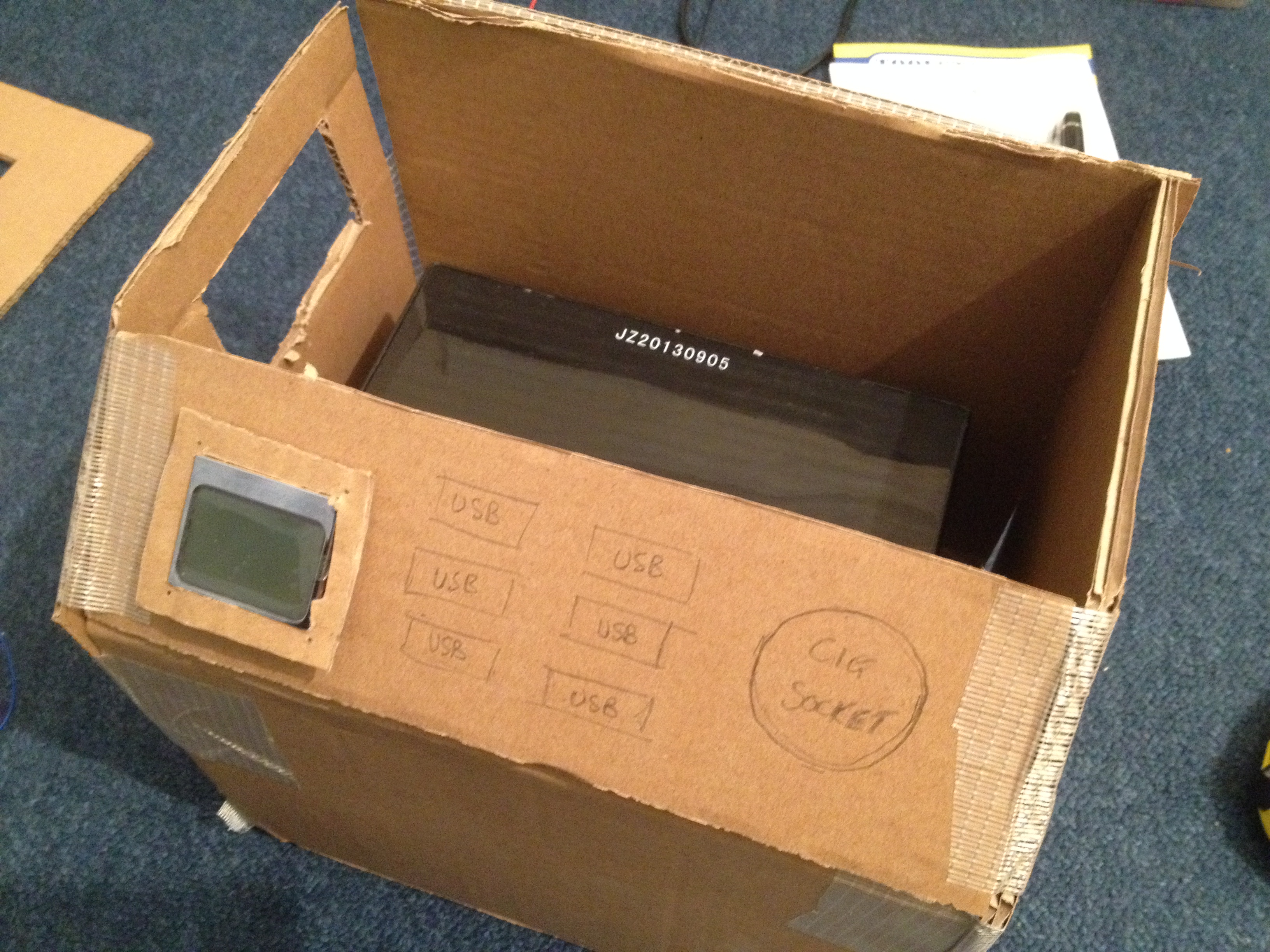
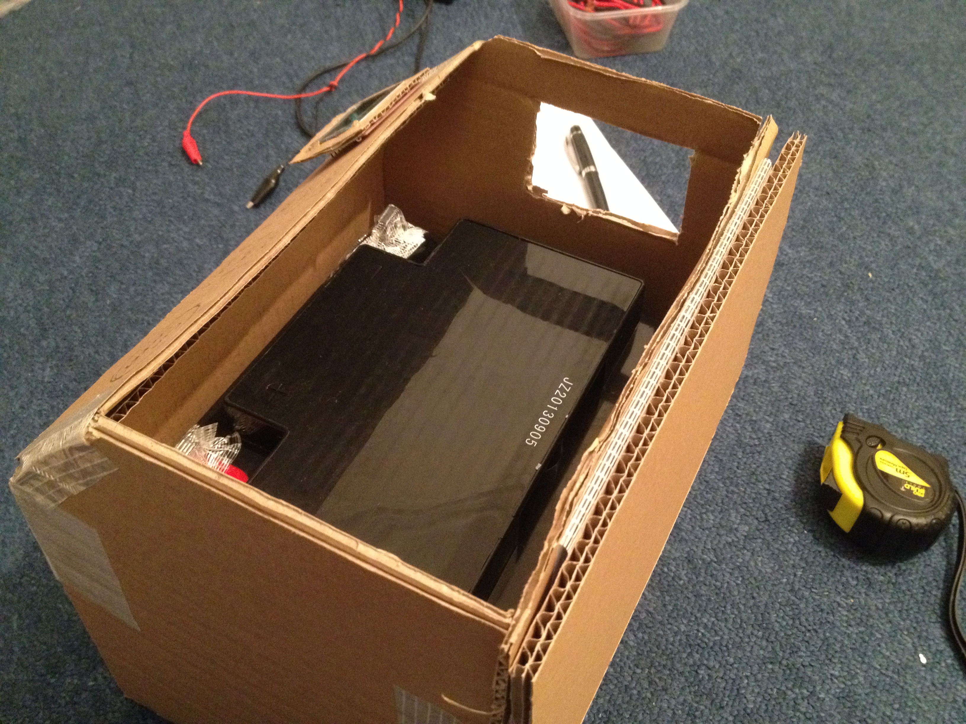
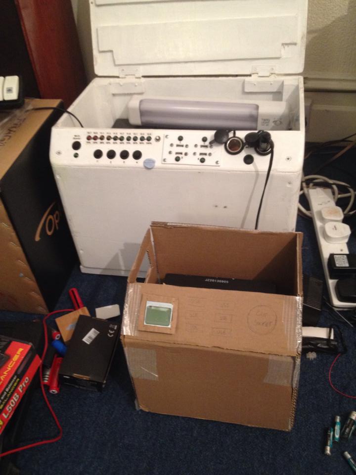
You already saw this from the last post but I began this project with a cardboard mockup of what I wanted the final outcome to be. In the end my final product was a few inches bigger in all 3 axis to accommodate tolerances and to make sure I did have room for everything. I am glad I opted for this as it turned out well.

IMG_2623 IMG_2624

I just used scraps of cardboard I had lying around for this and some sellotape. My measurements were primarily based on the battery size and I had originally intended to just put the inverter on top of it. I changed my mind last minute and made the box wide enough for it to go to the side of the battery instead (you’ll see this space later). Suffice to say, the cardboard mock up did help iron out some problems before the final box was made.

The wooden box

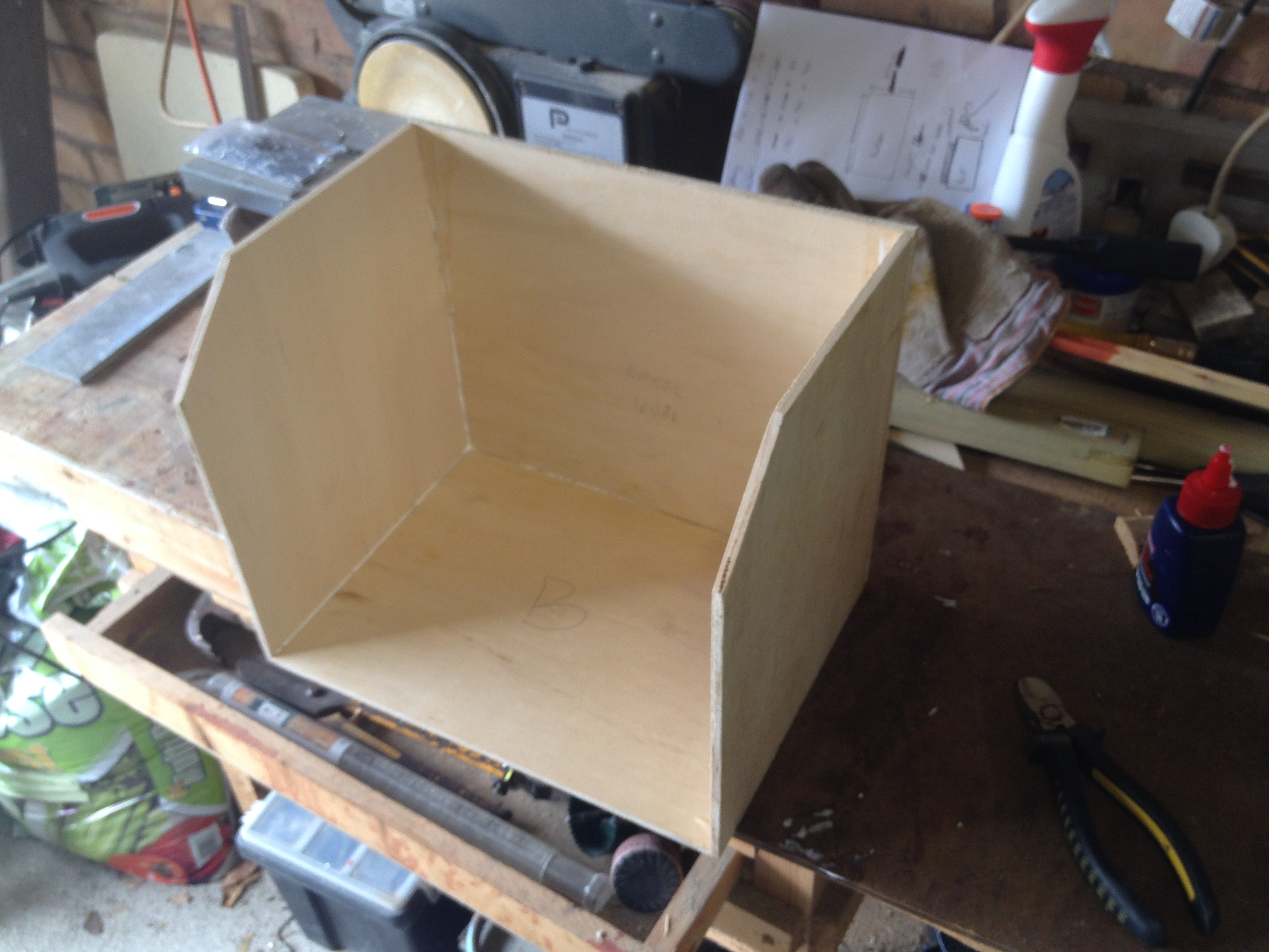
Just like the previous boxes, I opted for wood as my material of choice because it’s relatively cheap and easy to work with (not to mention easy to find) unlike plastic or metal. I chose 6mm plywood which seemed a bit thin at first but once put together it worked out just right.

IMG_2683 IMG_2691

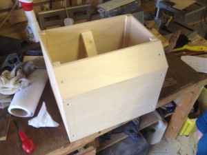
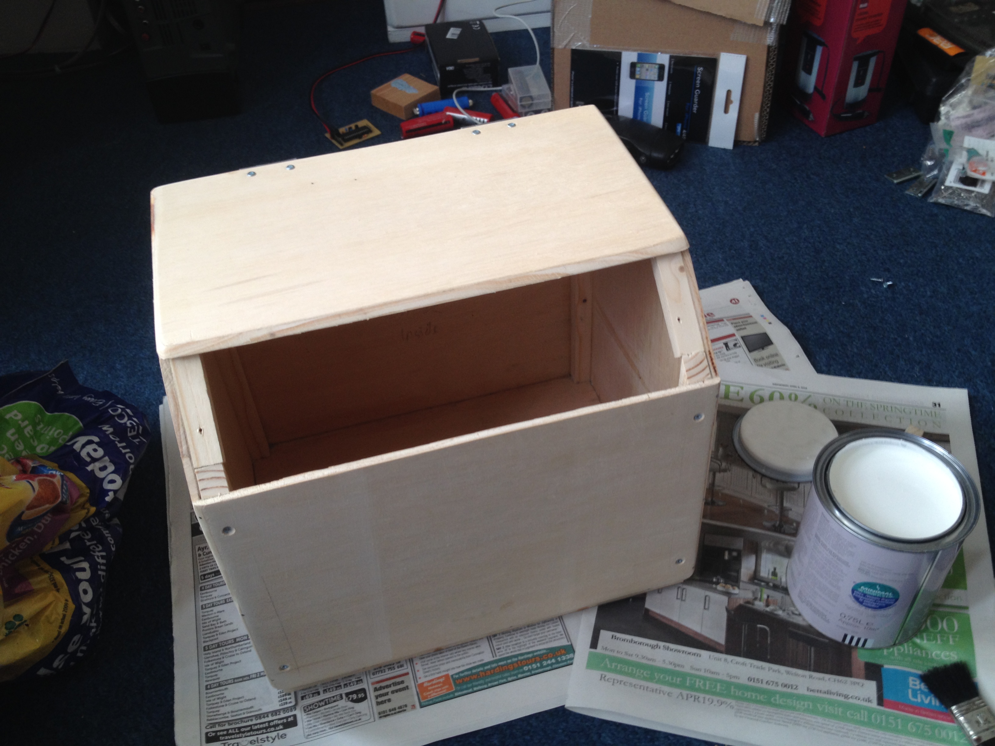
I chose to put the box together with small metal pins and wood glue. This was a delicate operation because of the thinness of the wood but with some help from a friend (actually he helped with pretty much all of it at some point or another!) we managed to put it together with only a few mistakes where the pins came through the wood where it shouldn’t. A little bit of wood filler fixed those mistakes. To further strengthen the box I put in 4 small corner posts which were glued in place and then 2 screws from each corner were put through to keep the sides on. To make sure the bottom was strong I made sure each side was tacked with pins into the bottom from the sides rather than it’s top where it could just fall out.

IMG_2712

To protect the box from the weather, I painted it with some plain white gloss. It needed several coats before it wasn’t showing any wood colour through it.

The electronics

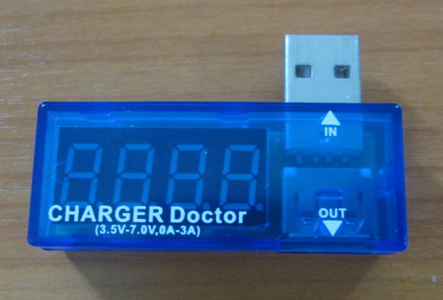
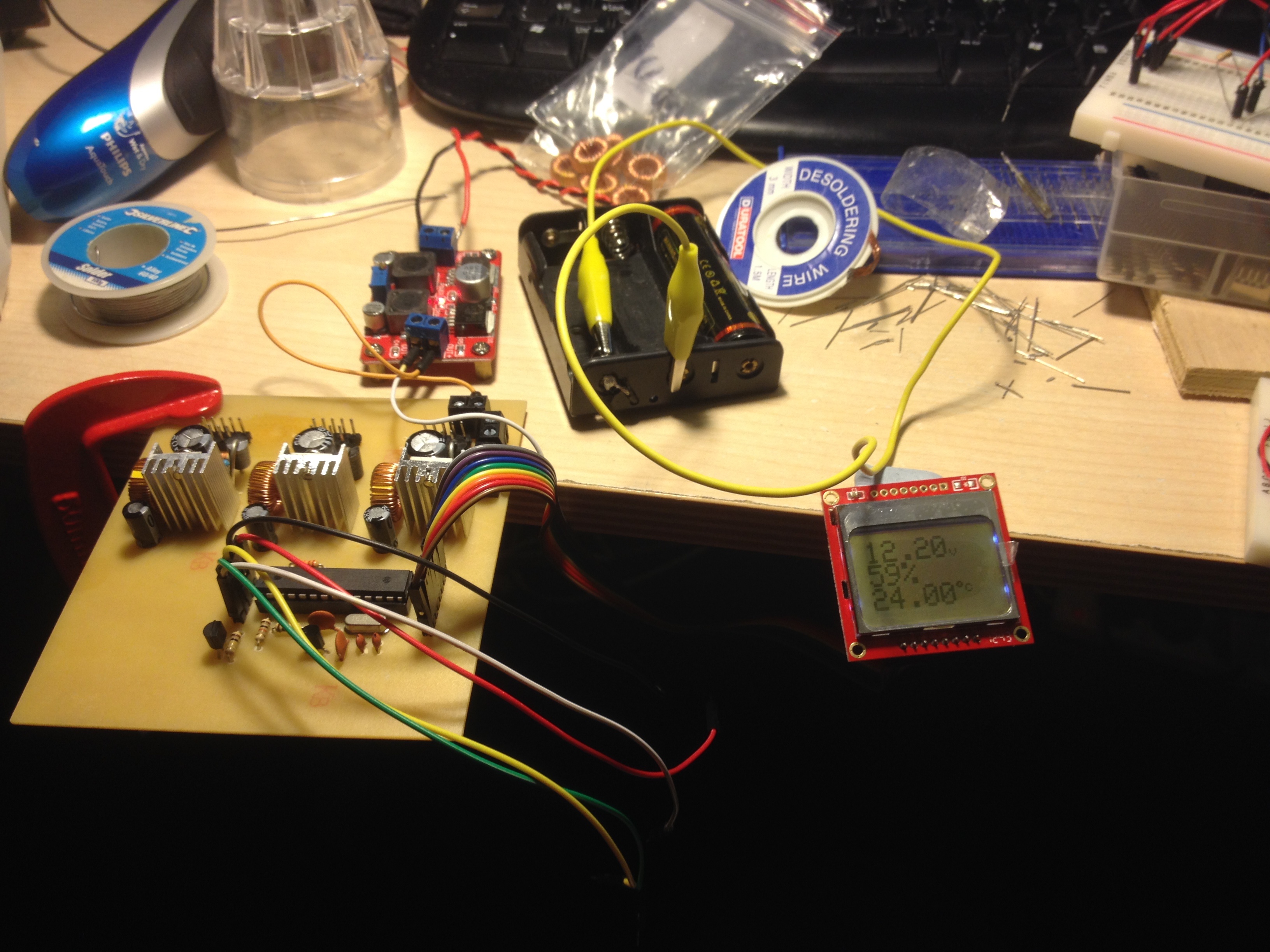
Probably by far the hardest part of the entire project was getting the electronics right. This has been in slow production since the beginning of the year. I was experimenting with power consumption for the LCD part of the circuit as this was planned to be on continuously. If the power consumption was too high then it would use too much power from the battery to be worth it. The LCD was to be used as a voltmeter (and percentage meter) and temperature. I had originally planned to put in a current sensor but this sensor turned out to be too low resolution and unstable to be worth implementing so I opted to leave it out.

IMG_2696 IMG_2703 IMG_2704

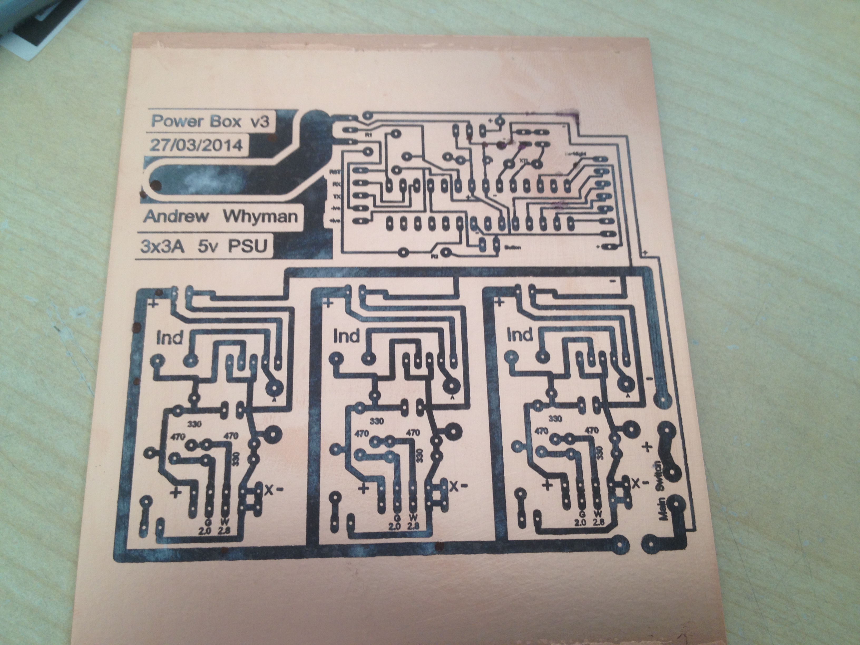
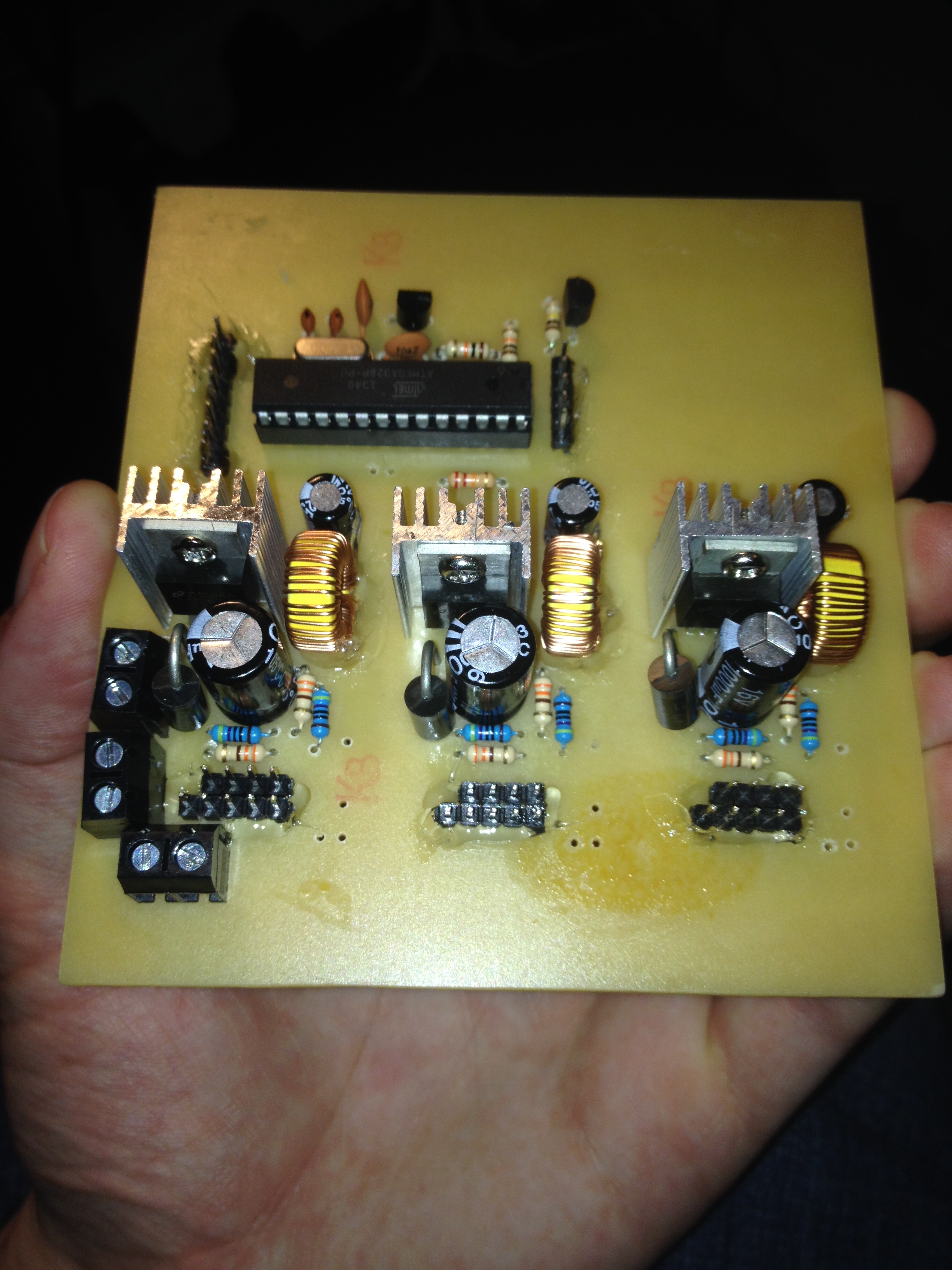
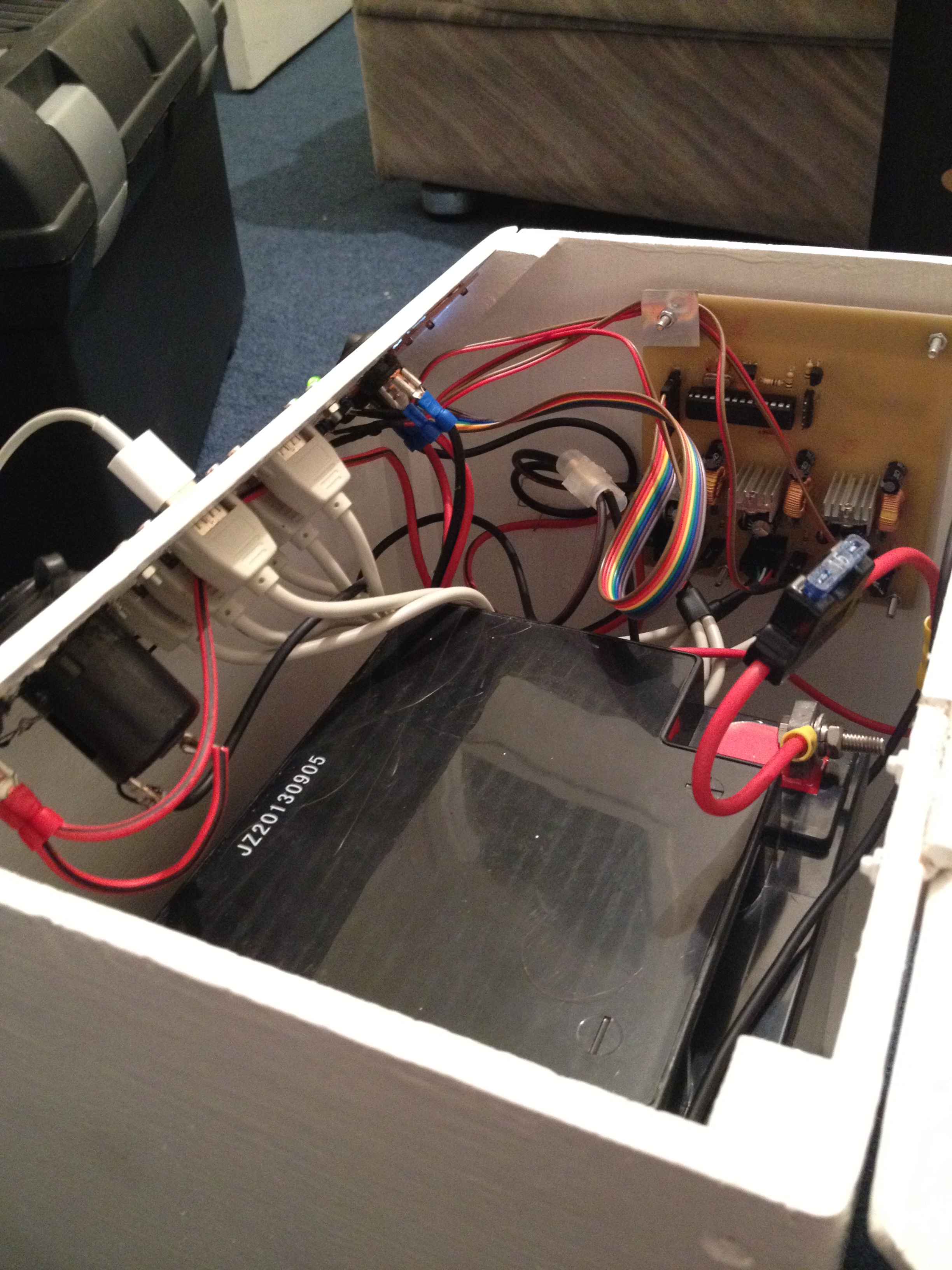
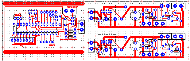
This board contains three 5v 3A switched mode power supplies with a resistor voltage divider for each of the data lines. This is set to allow the maximum current for any device plugged into the USB sockets. There is also an Arduino on board which is powered by a low quiescent current 3.3v regulator (standard regulators use about 5mA when idle, this one uses less than 1uA when idle which is a significant difference).

The whole Arduino circuit uses just an average of 2 to 3mA even with the LCD and backlight powered on. The backlight is using PWM to keep the brightness to the right level so that it can be seen in the day and night with ease. It took several attempts to get the circuit board to iron onto the board but after that it was mostly plain sailing.

A few minor fixes to the PCB were needed because the ironing process isn’t the best but with a little skill and patience these turned out not to be a problem. The one mistake I did make which I wish I had tested before making the board, was the spacing of components. The power connectors on the left side of the board were very close to one of the power supplies, and the diode and capacitor on the power supplies were a little close too. however I didn’t realise this until I’d already put most of the components on and soldered them so it was a bit late to go back and try again.

The front panel

The front panel layout was not something I thought about until I knew what size it was going to be. This was determined  quite late in the build process.

IMG_2710

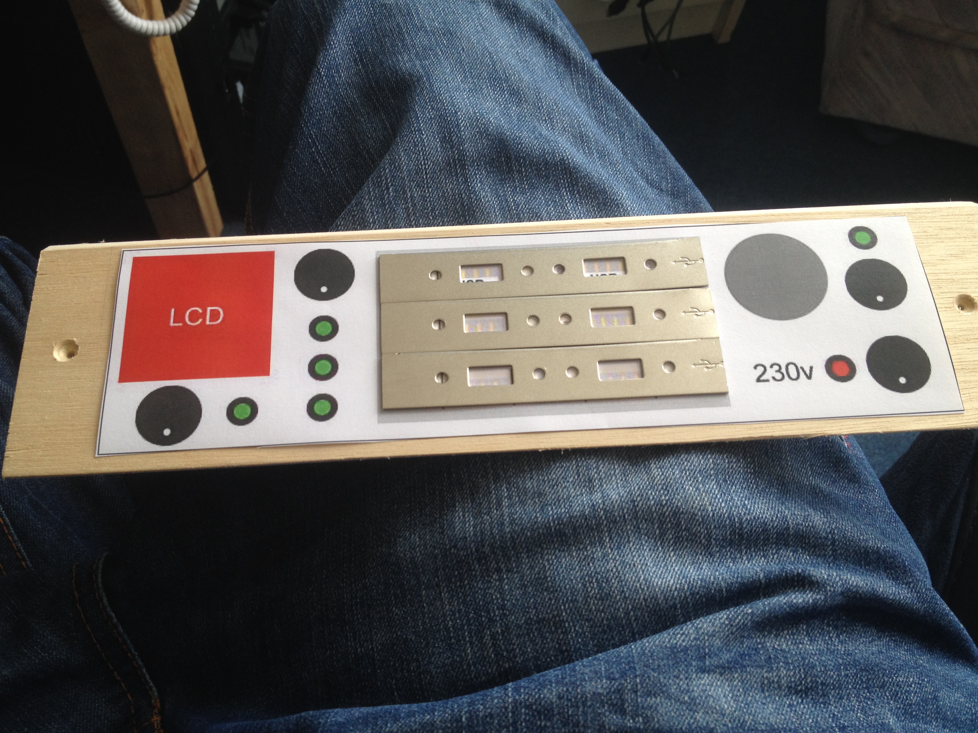
I decided to use the same process as the last power box and use photoshop plus real measurements to make my layout on the computer and then print it out in actual size. This makes moving things around to get the right layout much easier than drawing them on paper.

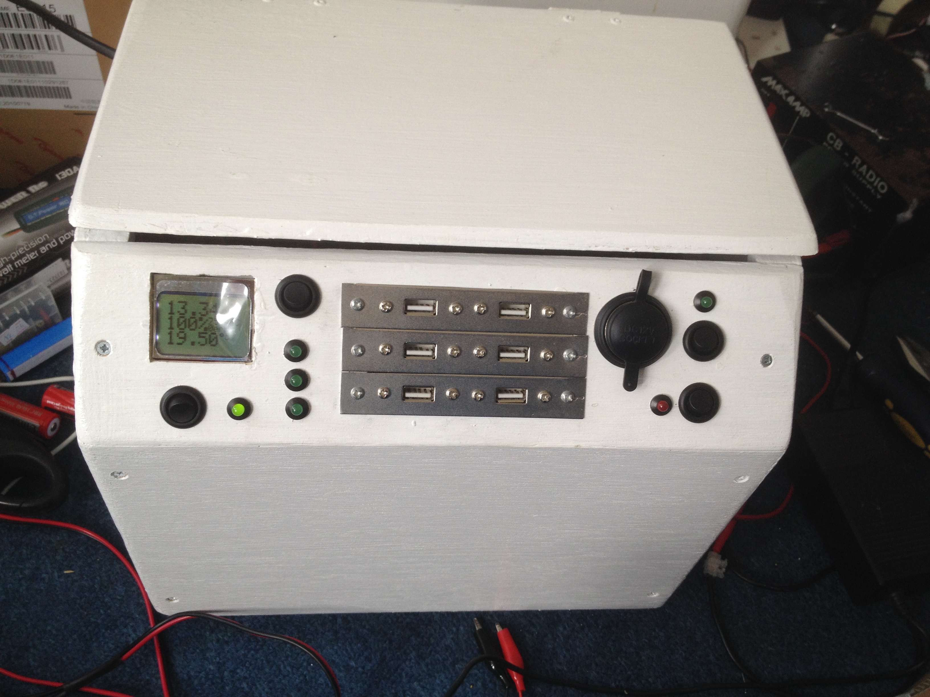
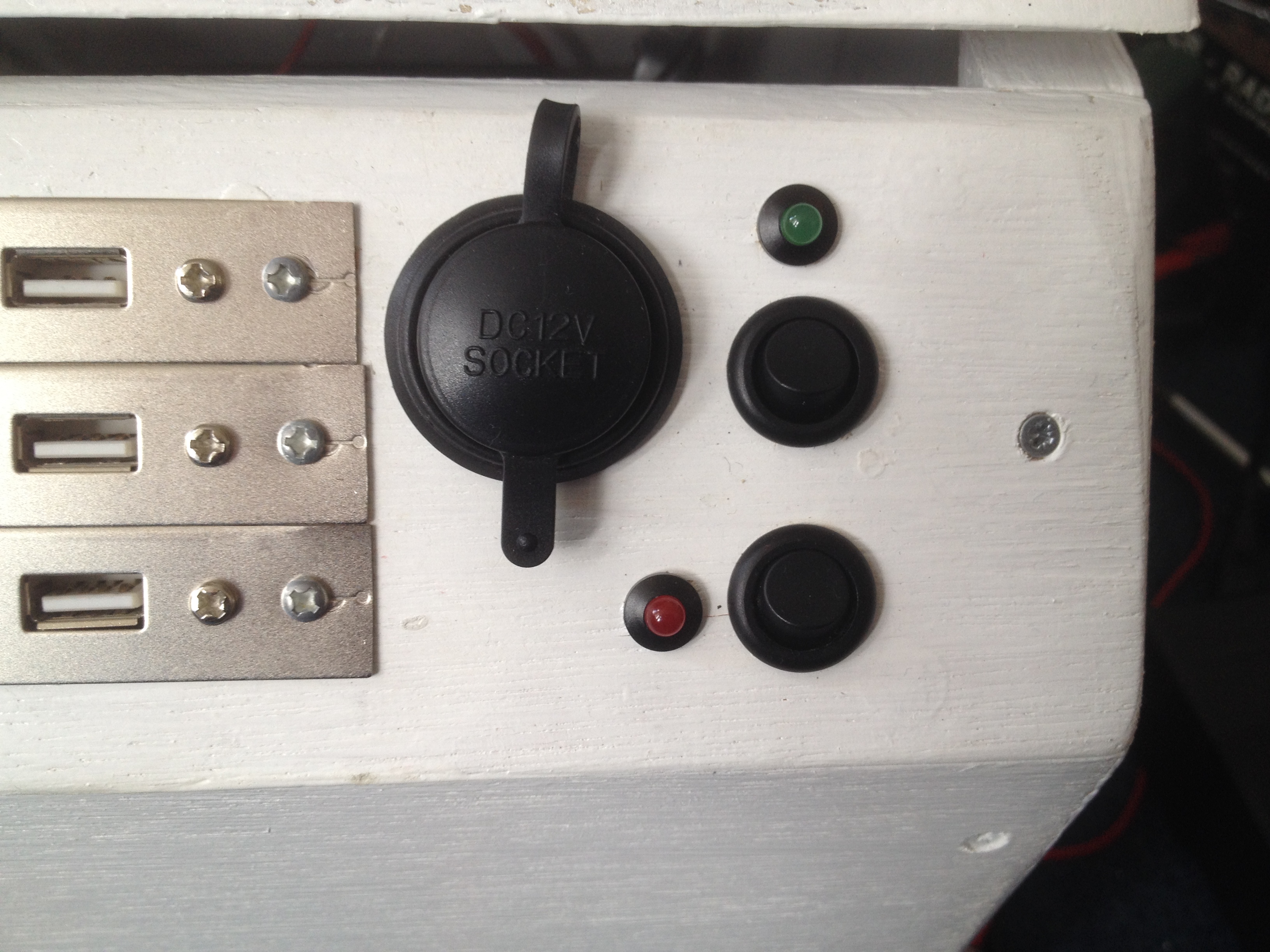
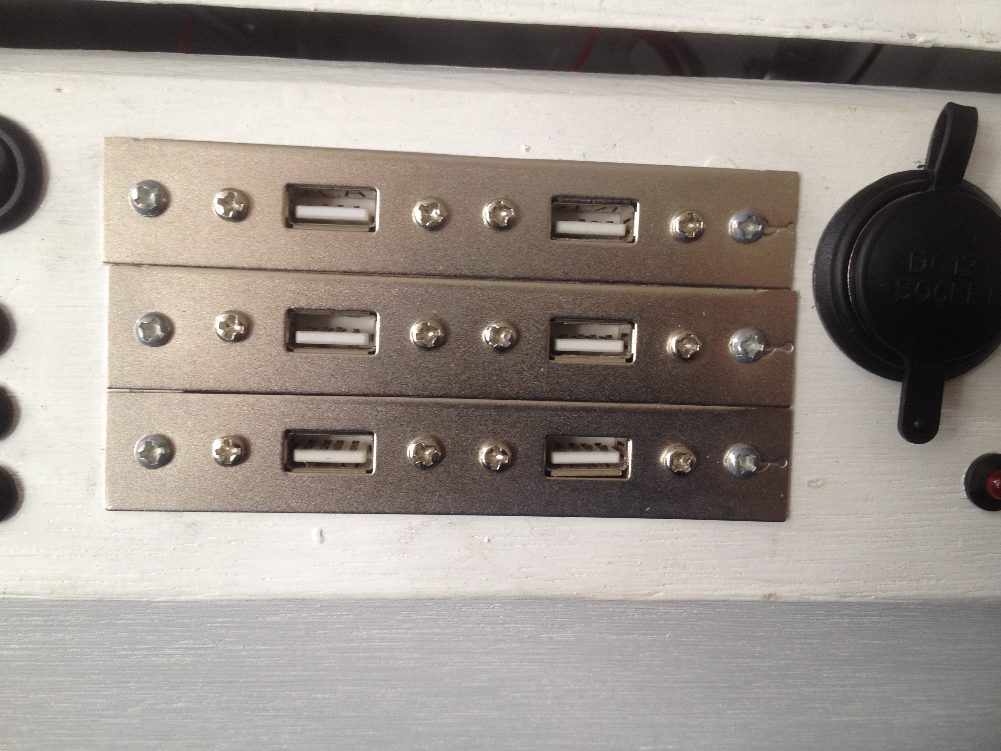
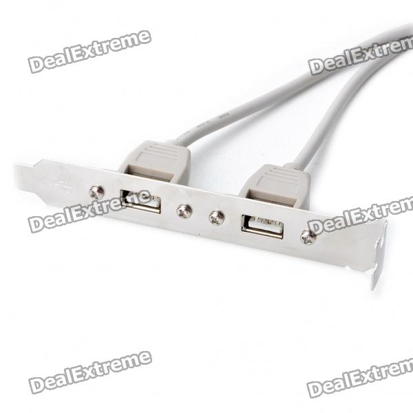
From left to right we have the LCD and main power button and LED, then a power switch for the USB sockets and 3 LED’s to show that the outputs are working. Then there are the USB sockets which are wired in pairs (left to right). We then have the cigarette lighter socket, it’s power switch and power LED, then under that we have a switch for the inverter along with a power LED.

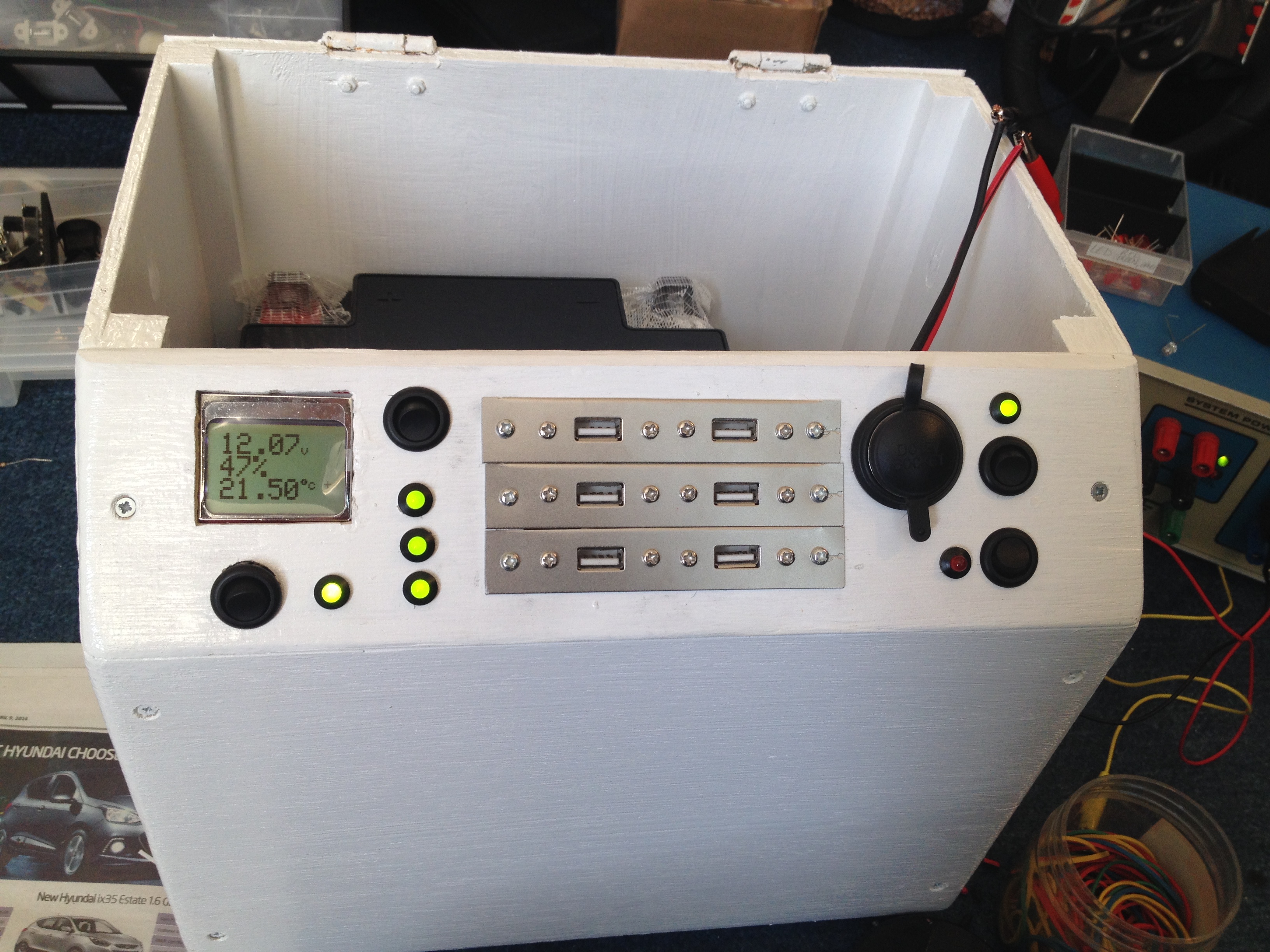
I had to drill out each of the different holes with just the drill bits I had lying around of which they were far too small for the cigarette lighter socket and LCD, so I used a coping saw for the bigger holes. The LCD was a tight fit and I still haven’t figured out a way to keep it in place. Thankfully the LCD fights tightly to the point that it holds itself in, but a moderate push will make it come out. I don’t want to glue the LCD in just in case it ever needs replacing.

IMG_2723 IMG_2815 IMG_2814 IMG_2725

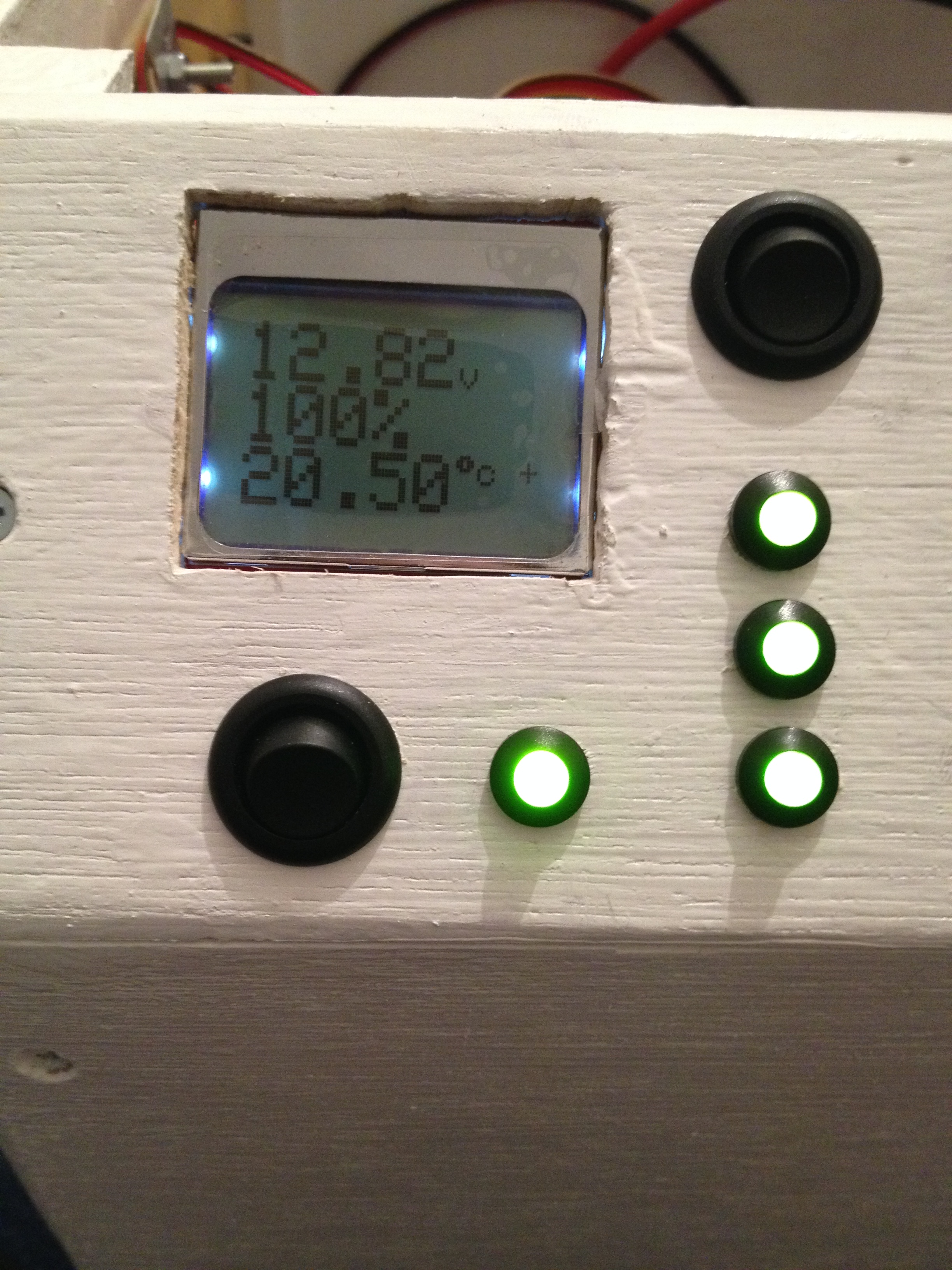
Above is the completed front panel and working LCD (this was running off a power supply for testing).

The arduino code

The arduino code was probably one of the biggest pains of this project. It should have been easy but because of the power consumption requirements I was forced to look into code that was help with power savings. The biggest power savings came from using 3.3v instead of 5v, and I also looked into using a lower frequency for the “CPU”. This arduino natively runs at 16MHz. This was much too high really for what this project needed. I looked into how it could be slowed down and it was actually quite easy. This circuit now runs at 1MHz for the majority of the time.

I say the majority of the time, but that’s where the problems started. The temperature probe I used runs on the OneWire library which is carefully coded to certain timings. These timings are only correct at 16MHz so of course at 1MHz it failed to work. I had to make sure that whenever the temperature updated that it returned to 16MHz whilst it probed the temperature and then it could return to 1MHz again. This happens for just a fraction of a second so power consumption is minimised.

There was also a problem which I found later and never really resolved which involved the voltage reading becoming wrong. I still don’t know why this happens but on occasion it would read incorrectly until the circuit was reset at which point it would be fine again for a random amount of time. To prevent this I ended up putting in if() statements to check the boundaries of values. If it went outside of boundaries it would initiate a reset. The easiest way to do this reset was through the arduino watchdog. This is a separate timer whose sole purpose is to reset the arduino if the timer expires. If the boundaries were exceeded, I initiated a delay that exceeded the timer so that it would reset on it’s own.

I originally set this to 2 seconds as it never took longer than 1 second to update – or so I thought. The box was completed the week before my camping trip to Silverstone for the racing so I took it with me for charging our phones. When we got there the LCD wouldn’t come alive, it kept rebooting. 2 seconds when it was colder wasn’t enough for it to initialise. Eventually it did end up starting but it was hit and miss. When I got home I changed it to 4 seconds but I haven’t had chance to test since. I imagine it is probably OK.

The end product

The final box is not actually complete. I still haven’t put the inverter into place as I haven’t figured out a way to keep it in place and I’m still not yet sure if I want to put it in. I’ll decide this at a later date.

As for the rest of it, the wiring for sure is much better than the last box and doesn’t look like random spaghetti!

IMG_2728 IMG_2812

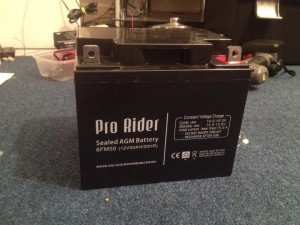
So am I happy with the end product? Definitely. The battery capacity is almost half that of the last box but the age of the battery in the last box meant it was actually holding less than the new one! (90Ah which was really 33Ah vs the new battery which is 50Ah).

The total cost? I’ll be honest I haven’t kept a record but tallying it up off the top of my head it will be around £150 plus a lot of effort. You do have to remember that this is a bespoke product so nothing like it in this form exists.

There are some items missed off this write up such as the battery clamps etc, but I wanted to point out the finer details instead. And like I said at the beginning, I didn’t document it as I went along. This was all of the top of my head!


New Power Box Mock-up

Posted by under Electronics, on 23 March 2014 @ 11:22pm.
battery50ah
The new 50Ah SLA battery

If you’re familiar with my blog then you’ve probably read this post about my power box that I built for camping. It’s served it’s purpose well over the last couple of years, but recently I discovered that the battery was starting to get weak. The 90ah SLA battery inside is about 6 years old now and when tested I found it only holds 35% of it’s original capacity. Considering it’s size, it was time to replace it with a new one.

When going over ideas for the new box, I realised that 90Ah was probably a bit on the large side. Now that I have the 10W solar panel to go with it, the box didn’t really discharge much last year when we were camping as the solar was keeping it topped up. Therefore I decided to instead get a smaller battery as a replacement. What I settled on was a 50Ah SLA battery instead (see picture 1).

powerbox3

Old box vs new box mock-up

Now because this battery is much smaller than the 90Ah battery, I decided a new box was in order as well as the original is already way over-sized for what it’s containing. I found that the easiest way to design it was to make a cardboard mock-up so I could check everything fits (see picture 2). As you can see the size difference is huge, there is at least a 40% reduction. I decided to make it more compact than the first one. The original box was over-sized so that I could fit in various things like the solar panel (pure luck this fitted), lights, chargers, etc. This time I won’t be doing that purely for space reasons. There was a lot of wasted space inside it.

I’m able to make the front panel smaller on this new box too because I’m introducing the Arduino powered voltmeter (and temperature meter). This takes over the function of the LED bar on the old one. In fact, let me do a breakdown of the features this new box will have:

– Arduino powered voltmeter and temperature display (backlit)
– 6x 1-3A USB ports (current rating undecided at the moment)
– 2x cigarette sockets
– 5A solar charge controller + socket for the solar panel

Possible additions:
– 1x 600w power inverter  (undecided if I will include this)
– Outside access to the +/- terminals for jump-starting/charging

One of the biggest concerns I have at the moment is being able to fit the USB power supplies onto a single board. It will depend on whether I use 1A or 3A power supplies. The 1A power supplies have proven very reliable and all of them still work great. The 3A power supplies are essentially exactly the same, except it’s an LM2576 (3A) instead of LM2575 (1A). The biggest problem is heat. At 3A they generate a LOT of heat, 2A is the safest I can get away with using the same heatsink. However there is no way to limit them to 2A so I will be taking a risk by using the 3A supplies and splitting between 2 ports. Phones typically will only use 1A or less anyway so there shouldn’t be much of a problem. Finding one big heatsink for them all would be a nice option but heatsinks are hard to find in the right shape and size. So I am caught between which one to use. I will likely go 3A for simplicity and hope for the best (I.E. hope they don’t overheat), otherwise I need 6 supplies instead of 3. Both circuits use the same footprint regardless (minus a bigger heatsink if chosen).

usbports
The panel mount USB ports I chose from dx.com

The panel mount USB ports will be mounted on the front on the aluminium plate they come on for ease of mounting. I learned last time that they’re hard to mount so I’ll save the problems this time and just use the plate it comes on, plus it will keep them nice and steady and hopefully neat too. The header sockets it comes with also makes it nice to plug into my board if I properly design it to use the header pins. I’m thinking about neatness here as the last one was terrible. Considering I intend to take this across the border into France when I go to Le Mans it can’t look like an explosive device of any kind otherwise I might be questioned! Neatness also minimises risk of short circuits etc too.

For now this is about all I can add. I will be getting the plywood and paint etc, at some point in the next week or two after I get paid. Then it should take me a weekend or two to build the box after I make the final measurements, and then a week to do the electronics. After that it should be good to go! This needs completing ideally before I go to Silverstone but the old one will still be there if it’s not, otherwise it needs doing before Le Mans so I have plenty of time (just over 2 months).

I’ll post some more updates here when I do more work on it, including the schematics for the Arduino display if I remember.


I don’t like being ripped off!

Posted by under Electronics, Rants, on 17 November 2013 @ 1:16am.

A few weeks ago I bought some 81650 Lithium Ion batteries off eBay as I wanted to test them in a number of applications for some possible future projects. Before buying I had read some reviews on how poor these batteries often are in yielding the rated capacity, but I found a few sellers on eBay that didn’t have many negative feedback and decided they would probably be OK. I went ahead and bought them, and week later they turned up.

I already have a smart lithium charger that was capable of telling me the capacity of the batteries when they had been charged (basically how much power it had put in them during the charge cycle). This is all I needed to test them but I also recently got a power meter that could do the same when discharging them too. I set to work trying to check them but immediately I knew something was wrong. I started a discharge with a 0.5A load and the voltage dropped very quickly. I first thought this was due to them being flat already so I decided to put them on charge first. I set the charger up for 3000mAh capacity and a maximum 3A charge rate, which is normal for these batteries. I set the charger going but immediately the voltage hit 4.2v and only pushed about 0.4A into the battery. I gave it the benefit of the doubt and let it charge anyway.

ultrafire-vs-trustfire

My limited experience shows Ultrafire have low capacity compared to Trustfire. Not all scenarios might turn out this way.

15 minute later the charger beeped to say it was fully charged. That was way sooner than I expected. I looked at the charge capacity and it was small. I don’t remember the figure but it was under 150mAh. So anyway I repeated my original test and let it run at 0.5A for a little while. The same voltage drop happened but I let it run. Less than 30 minutes later the batteries were showing 2.5v/cell, which is dead. My discharge meter read 210mAh! This is over 20x less than the rated capacity. I repeated the charge and discharge test a few times to be sure but it wasn’t changing.

As it turns out, these batteries were all duffs. They likely came out of old laptop batteries or similar, got re-labelled and shipped out as new. It’s safe to say I was pretty miffed at being ripped off. I wasn’t going to get stuck with them so I contacted the eBay seller who was happy to help. He asked me how I tested them so I told him and I even gave him the make and model of my charger and power meter. He didn’t argue he simply asked if I’d like a full refund, to which I agreed. He didn’t even want the batteries back. Something tells me he knew they were bad, despite the fact he told me he’d never had returns on them before. All 4 batteries that I had bought came out the same. Had it been one bad one I wouldn’t have been too bothered.

Anyway, I was refunded on the duff batteries so I set about looking for better ones. I decided to look on one of my favourite online shops, dx.com. I’ll be up front and say it’s a Chinese site but with a difference. The stuff they sell is actually half decent and they are much lower priced than other places. I’ve never had a bad purchase from them to date and I’ve bought a dozen things from them.

It didn’t take me long to find some batteries on there with good reviews. They claimed 2400mAh out of the rated 3000mAh. While not perfect it was a lot better, and the reviews were from people who had bought them too so I was inclined to follow them. Knowing the site has been good in the past helped too, so I didn’t hesitate to buy them. They took about 2 weeks to arrive and they came today. I did a quick initial charge, and then set about discharging them with the same 0.4-0.5A load I did with the others. It took a while, but I eventually ended the discharge test with a 2300mAh result. I then charged them and got the same amount put back into the batteries.

Success!

In case you’re wondering, I originally bought “Ultrafire” batteries which are cheap knock-offs of the “Trustfire” ones I bought in the end and they worked. My advice here would be to steer clear of Ultrafire and stick with the better brands like Trustfire. Better still, you could buy Sony batteries or another well known brand.


Camping 2013 and Solar Power

Posted by under Electronics, Life, on 4 August 2013 @ 11:27pm.

I got back from camping yesterday, and what a week it’s been. We went back to Shell Island this year as we really enjoyed it last year. Unfortunately we didn’t get to go on the beach much last year as the weather was awful compared to this trip. There was still wind and rain but in between we got serious amounts of sun so we were able to get to the beach a fair bit this year! Some days it was so hot that on one of them I managed to get sun burned in just a couple of hours even with SPF30 cream on! The rain we got was a cracking amount too… If I were to guess it looked like a full days worth of rain fell in 20 minutes. It went from totally bone dry to a sodden puddle laden field in just 20 minutes. I have never witnessed rain that heavy before.

camping-very-wet

The rain was so bad that 2 of us had to move our tents because a few inches of water had settled underneath! My tent is a few years old now so it’s not as waterproof as it once was. That showed during this rain because it leaked from every possible place it could. Even after moving it the rain was still coming through on light showers so I had to put a spare tarpaulin over the main sleeping area to keep it dry. Thankfully the underside wasn’t leaking as much. I’m still going to get myself a new tent though as it is about time it was replaced.

Getting onto the island was fun this year too. When I arrived (on my own this time but meeting up with others, many of us arrived at different times this year), I was stopped in my tracks at the last 500 yards by the tide. For those who don’t know, the island is not an island as such but it is tidal. Some days the tide covers the road by about 1-2ft making it dangerous to cross by car. I knew it was going to be covered but wasn’t sure how much. Anyway I waited in line for about 45 minutes before I was able to get across. I didn’t want to go through the salty water, but everyone else was doing it and I would have held up the line if I didn’t move along! Thankfully it wasn’t a lot and the excessive rain we had some days cleaned off most if not all of the salt.

camping-10w-solar-panel

As repeated every year, my power supply box was once again a center of attention and use by everybody on the trip. One of the guys met a friend on the site and even showed it to him, and he was also impressed. This year not only were phones were charged and Nintendo DS’s charged, even some portable speakers which give much better sound quality than a phone needed a charge too. This year however was different in one more way. Unlike previous years, this time I took along a small solar panel. The last time I did this was in 2006 when I took my jump start pack, CCFL and 2×1.5w solar panels. The panel I took this year was a small 10w panel I got off ebay for £20. 10w doesn’t sound like much (and in reality it’s not) but it was enough to prevent the battery going too low.

Last year the power box was so dead that the LED voltmeter didn’t even register a single light. This year, we returned home with 60-70% showing on the box and that was even with much more use of the power inverter compared to other years. I’d call that a big success. I don’t know how much power was generated or used but clearly it was quite a lot over the course of the week. Next year I will have a new setup for the box which will incorporate a digital meter run off of an Arduino along with current sensors (hopefully) which will be able to tell me how much power I have generated and how much I have used. I do need to do some more testing and experimenting with these however. The blog will be kept up to date on developments with this.

Next year I hope to have a 20w panel, a smaller battery (to save weight), the new circuit based on the Arduino, more powerful USB sockets and more of them in general, an integrated and hard-wired inverter with a socket on the front and perhaps more. It’s a big project but it’s keeping my basic electronics hobby happy.

Anyway, until next time…


New Electronics Project – Power Box V2

Posted by under Electronics, on 20 June 2013 @ 10:41pm.

Just a quick note before I begin, the Peugeot 306 I mentioned in my last post was sold last week. I managed to make back what I paid for it so it was no loss for me at all besides the time and worry spent over it. Still, you live and learn from your mistakes. There is one thing I have to note however. I sold the car through Auto Trader, and as soon as I signed up, less than a few hours later I had interest in the car. This was great, but then you read the e-mail and realise it was a scam. I got 2 e-mails both sounding very similar; A person needs a car for their son/daughter, but they are going away for 6 weeks and can’t view it. They will send payment via PayPal and they’ll pay the costs, and have a ‘shipper’ collect the car once payment is made. It all sounds perfect. What people don’t always realise is that they will then open a Paypal complaint and claim their money back, and there is little you can do to stop it. Auto Trader recommend you ignore these types of e-mails. I actually edited my advert to say phone calls only and cash on collection, as the scammers won’t call you or deliver the cash, so they ignore the ad.

———————————-

power-box-v2-circuit

The (incomplete) circuit for the powerbox v2. Left: Arduino. Right: 2x 5v @ 3A Switched Mode PSU’s.

Right, onto something more interesting. I decided earlier in the year to make version 2 of my power box (v3 if you include it just being a box). This one will be updated to include a digital voltmeter based on the Arduino. This also allows me to put in various other things on the screen too such as current draw, solar charge current, temperature, etc. I’m also upgrading the USB sockets from an LM2575 to the LM2576 which is a jump from 1A to 3A output. I’ve decided to split the 3A between 2 USB ports (perhaps 3, I don’t know yet, most likely 2 though) so that it can handle tablet PC’s and more modern phones. Some tablets won’t charge unless they get at least 1.5-2A of power and you never know, someone might want to charge one.

I’m also going to wire up the inverter to a proper socket this time and have a power switch on the front so you don’t have to mess about with opening the box to use it. This was a massive pain and had the risk of it being wired up incorrectly too.

The biggest change however is that I now have a 10w solar panel to charge the battery when we’re away. It is small enough to fit in the box but powerful enough to offset the use of the battery. It won’t fully charge it if we’re using it, but it will help stop it going flat as quickly. Last year we flattened it in the week (it was as dead as dead gets the day we left). This damages the battery if you do this so I would prefer to keep it topped up by use of solar. Here is a bit of maths…

The battery is 90Ah (so you can draw 1A for 90 hours until it’s dead, theoretically).

The solar panel, on a good day will output 3Ah (0.6A x 5 hours good sunlight) which is about 36Wh, plus perhaps a bit more when it’s indirectly in sunlight. I intend to roughly calculate this with the arduino’s solar input current.

Assuming a phone battery is 5Wh, I can charge roughly 6 phones per day from solar alone without using any battery power. This is assuming the solar panel does output 0.6A for a minimum of 5 hours and the system is 100% efficient.

Of course, it’s never perfect and when you want solar power the sun goes in, so these figures will likely never be reached. I won’t know for sure until it’s tried out for real.

Regardless, it’s better than having no solar panel at all. Over the course of the week, I could put 20Ah of power into the battery from the solar alone, and if we use what we used last year then it’s a win win situation. I do of course have use of the car if it does go flat. A 15-30 minute blast on the jump cables will sort it out no problem.

Anyway, I’ve been ordering parts for the project this evening so I can hopefully get it completed before camping this year. If not, I still have the old faithful box from last year instead which works just great. I’ll keep the blog updated with developments on this as I go along.


I have joined the dark side and purchased an iPhone, plus a rant about O2

Posted by under Electronics, Rants, on 8 July 2012 @ 7:06pm.

I have finally joined the world of Apple lovers and bought an iPhone 4S! For those who don’t know why, you should probably read my last blog.

Getting the iPhone was no where near as easy as it sounds, as I will explain now. But before I start, I advise anyone who wants to get one to go to a 3rd party store and not your network to get one…

Anyhow it all started after I was sick of the issues with my last phone, the LG Optimus 2X. I thought it was time to get myself a phone I knew I could rely on to work when the time came and to hold a signal when there was actually one present.

I’m with O2 and have been for 6+ years. I’m quite loyal to them as they’ve been very good to me and signal is generally good everywhere, so I thought I’d try my hand at a contract. I’ve never had one before as I couldn’t justify the cost. I’m on pay and go and I spend less than £10 a month on credit. What can I say, I’m not a heavy user.

The cheapest contract with a decent allowance and phone payment was £36 a month. Over 2 years that’s around £850 or so (off the top of my head). That was fair to me, so I decided to go ahead and order it. I got to the last page of the order and it said there was a problem and to try again or phone the supplied number. I thought I may have entered some details for my bank card incorrectly, so I tried again. Same response. I wanted the phone so I decided to call them. On the phone I said I had tried twice already. The rep checked this and she could see 2 failed orders but there was no reason provided for the failure. We tried it over the phone instead, and 20 minutes later we got the same outcome.

The O2 rep suggested that my card was being declined so I should contact my bank. I went along with it and called my bank and she would call me back in 20 minutes. My bank said that 3 payments for £117 had left my account and there was no issue their end!!! 3x £117!!! I was very annoyed. I waited for the rep to call back. 30 minutes later she did and I explained the situation. She was confused at what had happened so she went to get her supervisor. After a short time on hold she returned and said that it failed because I failed the credit check!

By this point I was very VERY annoyed. How can I fail the credit check? My credit score is flawless. Hell, I’m paying for a car on finance and I had no problem getting credit for that! I’ve never missed a payment and I’m full time employed. Unfortunately the data protection act means she doesn’t have any information as to why I was declined and there was nothing she could do about it. She was very apologetic but it wasn’t her fault. Anyway I said thanks and hung up.

I decided to screw the contract and decided to buy it out-right. Yup, the full £500 up front. I didn’t have much of a choice since I wanted to stay on the same network, but not knowing at this point it would have been better to go to a 3rd party store like carphone warehouse, I went ahead with the order.

What I should have said was I TRIED to go ahead with the order. I got to the last page of the order process and it failed to go through. Now I was pissed off with O2, so screw them. I’ll take my money directly to Apple instead. I went through the order process for the 5th time that evening and I was granted with another failed message. GAH!!! Then it clicked. My card was probably blocked by the bank because of the nature of the purchase. On the phone I went again to find out. 10 minutes on hold and I confirmed with the rep that it was indeed blocked. 5 minutes of security checks and it was unblocked and the order finally went through.

2 days later, the phone arrives and I’m once again a happy person (for the most part, there were some little niggles but I got those sorted by yesterday).

Anyway, I’m still not happy with O2 for those things. It’s strange how people with a perfect credit history can’t get finance, yet somebody with no history (lets take for example some 18-19 year old friends of mine) because they’ve never had credit before, can get one without a problem! The whole credit score idea is crap if there is no consistency to the way they accept orders.

Anyhow, the ordeal is now over and I have a phone that works properly for once. Lets see how long this one lasts, since I’ve had 3 phones in 12 months now (Blackberry, then the LG Optimus 2X, now the iPhone!).


A rant about Android and device manufacturers

Posted by under Electronics, Rants, on 8 July 2012 @ 6:38pm.

Well, this is one most of you knowing me wouldn’t have seen coming. Ever since I first tried Android I have loved it as a phone operating system. It’s such a powerful OS for a phone and allows you to do things you never thought possible on a small device like a phone. However, there are several flaws with Android that make it a very bad OS. Let me explain what I mean.

Take Apple. iOS on the iPhone is tailored to the iPhone devices very closely. It was specifically written for those devices and because of this it doesn’t have compatibility issues. This makes it very stable and less prone to bugs because Apple control the software for a limited number of devices and they maintain it continually.

Now take Android. It’s got to be built for hundreds of different devices by different companies. Each of these companies must modify it to work with their phones at the driver level for their devices. The problem behind this is that it’s not just drivers that need modifying. They also insist on bloating Android out with their own crap bloatware and apps that most people probably don’t want or need. This makes it very prone to bugs and makes it unstable in some cases. Android device manufacturers however, do not appear to maintain the operating systems and drivers for their devices. They release one version and that’s it, job’s a done one, wham bam thank you very much for your money. Then they move onto a new phone and do it al over again.

The problem with Android’s approach is that there is no maintaining in this system. Once the phone is releases, it will probably never see any updates in it’s entire life because it’s such a short lived device the manufacturer does not think it needs maintaining. This sort of thinking needs to stop! Android is never going to be a good phone operating system unless Google themselves take some form of charge over it. They need to think like Microsoft does with their Windows operating system. Provide a base operating system and let people install drivers for specific devices instead. That way any bugs in operating system are Google’s responsibility and any drivers are the responsibility of the device manufacturer (or the chipset manufacturer).

If you’re going to make a device like a PC, it needs to work the same way. Windows itself is 100% stable, it’s the drivers and 3rd party hardware that makes it unstable. The same generally applies for Linux too. If Android worked this way as well, I think it would make the perfect operating system for phones.

Lets take my old LG GT540 and my LG Optimus 2X as a prime example for my basis. These phones both have very nice hardware (at least they did when they were released). I thought both phones were very solid (both still work despite the GT540 being a few years old). However they both had bugs that made me decide to get rid of them.

The GT540 had a bug in the stock ROM software that prevented data from working properly. When data connected, phone calls and text messages were prevented from coming through. Of course this is useless when it’s supposed to be a phone. Besides that the phone is not bad at all. A little laggy at times, but again this is a software issue as a reboot solves it as it gets a fresh reload.


Google need to adopt the same development method as Windows and Linux for Android

The Optimus 2X also had a bug that was present on the stock ROM. If you lost signal, sometimes it would not come back (even in a perfect signal area) until you rebooted the phone. It happened more often when you were in a low signal area, such as my work place, that meant it struggled to get signal. It also had another bug where the wifi would not stay connected when the screen was off, despite the option being set to “never turn off wifi”. Again this prevented the phone from being used properly. I tried another ROM on it (Cyanogen) and the same issue occurred. I narrowed it down to the baseband software (the firmware that allows the phone and radio to communicate with one another). If this were a hardware issue a reboot would not solve it. I am also not the only one to experience this issue as it’s all over the Cyanogen forums and nobody has a fix thus far.

So as you can see, Android has some serious bugs that simply should not be present. Other phones also have issues. Take my friend Tom as an example. He went out yesterday and bought a HTC One S. A brand spanking new Android 4.0 (Ice Cream Sandwich) phone that is a full 2 versions up from my Optimus 2X. Within hours he had issues with it. The wifi was glitchy and would not stay connected properly, and he could not delete synced contacts from Facebook. The wifi bug was documented online after a quick search with a “fix due in a future release”. Great, so until then he has to use expensive 3G data to go on the Internet on his device.

These bugs would not exist if Android took more control over the operating system, releasing patches and bug fixes when issues were found. Anything out of their control such as drivers can be dealt with more seriously by the manufacturers. This setup would make for a much more stable operating system. It’s proven to work, just look at Microsoft Windows and well supported distributions of Linux.

So I call out to Google (if anyone is listening) to employ this development method for Android. It’s a fantastic operating system, but if my phone won’t work as a phone, then it’s useless to me. For that reason I have moved away from an Android device as my phone and over to a phone I know I can rely on – an iPhone 4S.

Read my next blog for more on my iPhone purchase and the stories behind it.


Portable Power Box

Posted by under Electronics, on 12 June 2012 @ 11:12pm.

A few years ago for camping I wanted a box to hold a huge battery (12v 90Ah) so we had power for the whole week. This was for various items, mainly lighting and charging phones. However this box quickly became one of the focal points of the trips for everyone that had something to charge, be it a phone, camera or anything else.

The old power box
Last year, we burned out a dual port USB charger because we were all charging devices almost non-stop! With only 2 ports between 9 of us it was hardly surprising. To overcome this we needed a new solution, and this blog is the details outlining the improvements.

To begin with, I decided what we needed in terms of power. At the moment we had a 4 socket cigarette lighter splitter which we could plug numerous devices into. We also had a plug in USB charger which we burned out with a few days of the trip left. This of course wasn’t very good so we need a new solution to that. I also had a digital multi meter for monitoring the battery state of charge which was bulky and unnecessary, so a solution for that was also needed.

After careful consideration I decided on having 2 cigarette lighter sockets, 4x 1A USB sockets and an LED bar-graph style volt/state of charge meter. Each of the USB sockets will be powered separately and both cigarette lighter sockets will be on at once. The volt meter will be either push to make, release to break or push to make and push to break. As it turns out the switch I chose could do both depending on the pressure you put upon it.


USB and LED Volt Meter

After I decided on the specifications, I had to decide how I was going to make the USB ports and the LED volt meter.

For the USB ports I initially wanted to use the very simple and very cost effective LM7805 5v 1.5A regulator as this made everything very simple. However it turned out that these were simply too inefficient and got extremely hot without a massive heat sink to take away the heat. This made it infeasible to use. I needed another solution.

Eventually I found the LM2575, which is a switched mode 5v 1A regulator. This required additional external circuitry which was hard to find and a little expensive, but once built I realised how much more efficient it was. Virtually no heat was emitted from the regulator or the inductor that I had to use. The efficiency must easily have doubled. After careful planning and testing I eventually made the final board which is now used in the final product.

4x LM2575 - Final design

The final USB power board
This board coupled with 2 voltage dividers per output for the data lines made the perfect USB charger. This part was the hardest to get working given the issues I had early in the design stage, but eventually I prevailed and it works flawlessly.The LED volt meter presented it’s own problems. It relied on an LM3914 bar graph driver, similar to the kind you see on VU meters on audio equipment. It works the same way but rather than being a logarithmic scale this one is linear.

Having operated solar equipment for years I knew the voltage range I needed for the volt meter to work in order to understand the chemistry of the battery and it’s state of charge. This range is 10.5v (totally flat battery) to 12.6v (100% full battery while resting with no surface charge). As the driver works with 10 LED’s I decided on 2 red, 2 orange and 6 green LED’s with 0.2v separation between each. The scale would begin at 10.7v and go up to 12.5v which would indicate a 10%-100% state of charge (while resting).

The LM3914 was a pain to get it to work. The documentation to me isn’t overly clear and it took weeks to get it working, but eventually I found a plan online to go by and now it works perfectly, though to be honest the 10k POT could do with changing to a 1k POT with a 1k either side of it. It’s a bit sensitive to changes in my design. Below are both designs so you can choose which to use.

Left: The first design with a 10k POT
Right: Modified POT/resistors values for less sensitivity and more accurate adjustment


This circuit works for a variety of ranges but the minimum and maximum values are around 2.0-2.5v from each other depending on your voltage range. You will need to experiment. For 10.7-12.5v the value from minimum to maximum is about 2.0v. The potentiometer adjusts it. To set it up, set your voltage to 12.5v and turn the potentiometer until the final LED just lights up. Now set it to 10.7v and it should extinguish all but the final LED. It’s not 100% accurate but it’s a very good representation and that’s all I needed for this project. If you want accuracy, buy a digital volt meter instead.


The Front Panel

Once the two hardest electronics parts were out of the way I set about with the front panel design. This along with knowing the battery dimensions and other items that were going into the box, allowed me to set a size for the box itself. This part is entirely up to you to set based on your battery and other components including your front panel design.

I first set out on paper but quickly realised this was hard when mistakes were made. In the end I switched to Photoshop and used exact size measurements of my components. This is great when using Photoshop as you can also print to the same size onto paper and it remains accurate. This was the key to making my front panel. I measured each component and made a graphic in Photoshop, duplicating where needed to make my layout. Below is my final panel design. All graphics were created by myself in Photoshop but you can feel free to copy.

The final panel design with labels. Click to enlarge.


When making the front panel itself, I quickly realised the USB ports weren’t going to fit correctly, so I used some 1.6mm thick plastic to mount them instead. The wood panel behind had a hole cut in with some overlap for the plastic to be fastened with nuts and bolts. This allowed for a cleaner look and for the plugs to fit into the sockets cleanly with a good connection.


The soldering of the parts was a major problem for me. I ended up ordering a new soldering iron as my little 15w iron wasn’t up to the job. One mistake I made was trying to solder to the tabs on the switches. Don’t do this, you’ll only ruin your switches as I did by melting them. Instead get some push on crimped connectors instead and use those. I melted 4 switches in an attempt to solder to them so it’s not worth the risk or the money.

Always remember to heat shrink tube your connections to avoid short circuit where you can, and most definitely don’t forget to use a fuse! I used a 15A fuse which should be plenty to include draw from the cigarette sockets. Remember to carry spare fuses too!


The Final Product

Here is the final product. It’s by no means perfect, the wiring is awful and there are cosmetic defects, but this was my first try and it came out better than I expected. For that reason, I’m happy enough!

Future additions will be the power inverter and some carry handles as it’s 30KG in weight!


The finished product


Images of the inside with the battery and the electrics (messy!)
Click the images to enlarge


« Newer PostsOlder Posts »