Joule Thief Circuit – Power a white/blue LED from a 1.5v battery
I’ve seen this circuit around before, but it kept cropping up while looking at other electronics videos on YouTube. It’s called a Joule Thief, and it was designed as a simple solution to boost voltages from lower sources higher at the expense of more current draw.
This circuit is basically a DC to DC boost converter that uses a ferrite toroid coil and a transistor to oscillate. I’m not 100% sure on how it works yet (even though I built one but anyone can do that!) but there are two coils on the ferrite toroid which are connected in parallel. When oscillated they produce more voltage than went in as mentioned above at the expense of more current being required (remember the equation, power = volts * current (P = V * I). More double the current and half the volts is the same overall power). The transistor is what causes the oscillation by switching very quickly.
Here is a basic diagram I found on evilmadscientist.com.

You should be able to follow that quite easily. I would put a diagram on of the layout I used but I don’t have that picture to hand. Perhaps on my next blog on this I will put that on but a quick search should find you suitable images to work from.
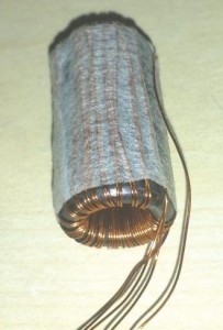
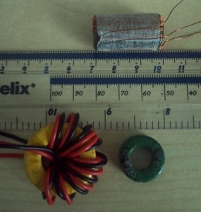
Here’s the ferrite toroid I used (and a bunch of others next to a ruler for size comparison). I wound it myself using ~0.25mm magnet wire and held it in place with sticky tape. The diagram I found used 20 turns but I ended up with 26. It still works pretty well. In fact I would have preferred more turns as when the voltage got too low on the input the output also dropped, thus the LED light output dropped drastically.
When the coil is wound you need two strands, so one long length folded in half. When winding, leave a few inches at the joined end and wind the rest both strands at the same time side by side (as you can see above). The end that is joined to both strands will become your positive input for both coils. The others are then connected to the base (through a 1k resistor) and the collector of a general purpose NPN transistor. The emitter is where your higher output will be.
There is likely some math behind the number of turns the coil needs given your input to get the required output. I haven’t discovered or looked this up yet. If you just want to power a white LED from a 1.5v battery, then 20-30 turns will suffice. I worked it out as 0.1v per turn but this might be different between ferrite toroids.
The beauty of this circuit is that it will work at very low voltages and will extract all of the power from your battery until it’s completely dead, not like most applications which will drop off at around 1.0-1.3v. This still leaves a lot of power left in the battery (up to 40% depending on brand!).
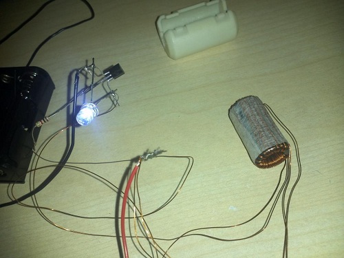
Here is my setup, as messy as it looks. This was my first test and I will be building more in the future which will be on a circuit board (actually it will be on veroboard (stripboard)).


