Camping 2013 and Solar Power

Posted by under Electronics, Life, on 4 August 2013 @ 11:27pm.

I got back from camping yesterday, and what a week it’s been. We went back to Shell Island this year as we really enjoyed it last year. Unfortunately we didn’t get to go on the beach much last year as the weather was awful compared to this trip. There was still wind and rain but in between we got serious amounts of sun so we were able to get to the beach a fair bit this year! Some days it was so hot that on one of them I managed to get sun burned in just a couple of hours even with SPF30 cream on! The rain we got was a cracking amount too… If I were to guess it looked like a full days worth of rain fell in 20 minutes. It went from totally bone dry to a sodden puddle laden field in just 20 minutes. I have never witnessed rain that heavy before.

camping-very-wet

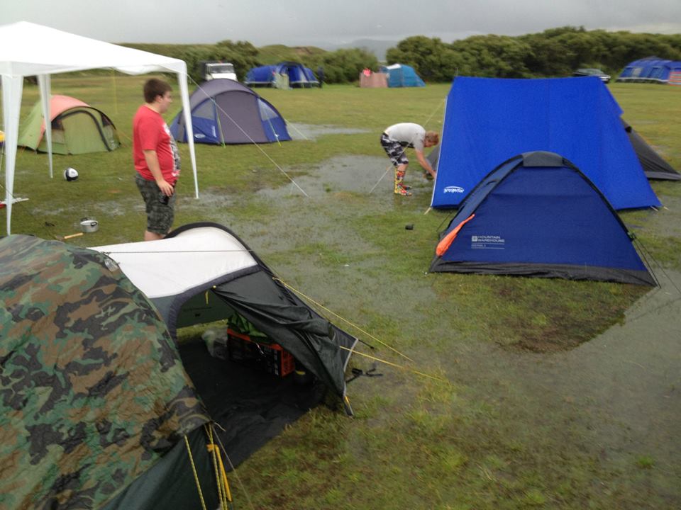
The rain was so bad that 2 of us had to move our tents because a few inches of water had settled underneath! My tent is a few years old now so it’s not as waterproof as it once was. That showed during this rain because it leaked from every possible place it could. Even after moving it the rain was still coming through on light showers so I had to put a spare tarpaulin over the main sleeping area to keep it dry. Thankfully the underside wasn’t leaking as much. I’m still going to get myself a new tent though as it is about time it was replaced.

Getting onto the island was fun this year too. When I arrived (on my own this time but meeting up with others, many of us arrived at different times this year), I was stopped in my tracks at the last 500 yards by the tide. For those who don’t know, the island is not an island as such but it is tidal. Some days the tide covers the road by about 1-2ft making it dangerous to cross by car. I knew it was going to be covered but wasn’t sure how much. Anyway I waited in line for about 45 minutes before I was able to get across. I didn’t want to go through the salty water, but everyone else was doing it and I would have held up the line if I didn’t move along! Thankfully it wasn’t a lot and the excessive rain we had some days cleaned off most if not all of the salt.

camping-10w-solar-panel

As repeated every year, my power supply box was once again a center of attention and use by everybody on the trip. One of the guys met a friend on the site and even showed it to him, and he was also impressed. This year not only were phones were charged and Nintendo DS’s charged, even some portable speakers which give much better sound quality than a phone needed a charge too. This year however was different in one more way. Unlike previous years, this time I took along a small solar panel. The last time I did this was in 2006 when I took my jump start pack, CCFL and 2×1.5w solar panels. The panel I took this year was a small 10w panel I got off ebay for £20. 10w doesn’t sound like much (and in reality it’s not) but it was enough to prevent the battery going too low.

Last year the power box was so dead that the LED voltmeter didn’t even register a single light. This year, we returned home with 60-70% showing on the box and that was even with much more use of the power inverter compared to other years. I’d call that a big success. I don’t know how much power was generated or used but clearly it was quite a lot over the course of the week. Next year I will have a new setup for the box which will incorporate a digital meter run off of an Arduino along with current sensors (hopefully) which will be able to tell me how much power I have generated and how much I have used. I do need to do some more testing and experimenting with these however. The blog will be kept up to date on developments with this.

Next year I hope to have a 20w panel, a smaller battery (to save weight), the new circuit based on the Arduino, more powerful USB sockets and more of them in general, an integrated and hard-wired inverter with a socket on the front and perhaps more. It’s a big project but it’s keeping my basic electronics hobby happy.

Anyway, until next time…


Portable Power Box

Posted by under Electronics, on 12 June 2012 @ 11:12pm.

A few years ago for camping I wanted a box to hold a huge battery (12v 90Ah) so we had power for the whole week. This was for various items, mainly lighting and charging phones. However this box quickly became one of the focal points of the trips for everyone that had something to charge, be it a phone, camera or anything else.

The old power box
Last year, we burned out a dual port USB charger because we were all charging devices almost non-stop! With only 2 ports between 9 of us it was hardly surprising. To overcome this we needed a new solution, and this blog is the details outlining the improvements.

To begin with, I decided what we needed in terms of power. At the moment we had a 4 socket cigarette lighter splitter which we could plug numerous devices into. We also had a plug in USB charger which we burned out with a few days of the trip left. This of course wasn’t very good so we need a new solution to that. I also had a digital multi meter for monitoring the battery state of charge which was bulky and unnecessary, so a solution for that was also needed.

After careful consideration I decided on having 2 cigarette lighter sockets, 4x 1A USB sockets and an LED bar-graph style volt/state of charge meter. Each of the USB sockets will be powered separately and both cigarette lighter sockets will be on at once. The volt meter will be either push to make, release to break or push to make and push to break. As it turns out the switch I chose could do both depending on the pressure you put upon it.


USB and LED Volt Meter

After I decided on the specifications, I had to decide how I was going to make the USB ports and the LED volt meter.

For the USB ports I initially wanted to use the very simple and very cost effective LM7805 5v 1.5A regulator as this made everything very simple. However it turned out that these were simply too inefficient and got extremely hot without a massive heat sink to take away the heat. This made it infeasible to use. I needed another solution.

Eventually I found the LM2575, which is a switched mode 5v 1A regulator. This required additional external circuitry which was hard to find and a little expensive, but once built I realised how much more efficient it was. Virtually no heat was emitted from the regulator or the inductor that I had to use. The efficiency must easily have doubled. After careful planning and testing I eventually made the final board which is now used in the final product.

4x LM2575 - Final design

The final USB power board
This board coupled with 2 voltage dividers per output for the data lines made the perfect USB charger. This part was the hardest to get working given the issues I had early in the design stage, but eventually I prevailed and it works flawlessly.The LED volt meter presented it’s own problems. It relied on an LM3914 bar graph driver, similar to the kind you see on VU meters on audio equipment. It works the same way but rather than being a logarithmic scale this one is linear.

Having operated solar equipment for years I knew the voltage range I needed for the volt meter to work in order to understand the chemistry of the battery and it’s state of charge. This range is 10.5v (totally flat battery) to 12.6v (100% full battery while resting with no surface charge). As the driver works with 10 LED’s I decided on 2 red, 2 orange and 6 green LED’s with 0.2v separation between each. The scale would begin at 10.7v and go up to 12.5v which would indicate a 10%-100% state of charge (while resting).

The LM3914 was a pain to get it to work. The documentation to me isn’t overly clear and it took weeks to get it working, but eventually I found a plan online to go by and now it works perfectly, though to be honest the 10k POT could do with changing to a 1k POT with a 1k either side of it. It’s a bit sensitive to changes in my design. Below are both designs so you can choose which to use.

Left: The first design with a 10k POT
Right: Modified POT/resistors values for less sensitivity and more accurate adjustment


This circuit works for a variety of ranges but the minimum and maximum values are around 2.0-2.5v from each other depending on your voltage range. You will need to experiment. For 10.7-12.5v the value from minimum to maximum is about 2.0v. The potentiometer adjusts it. To set it up, set your voltage to 12.5v and turn the potentiometer until the final LED just lights up. Now set it to 10.7v and it should extinguish all but the final LED. It’s not 100% accurate but it’s a very good representation and that’s all I needed for this project. If you want accuracy, buy a digital volt meter instead.


The Front Panel

Once the two hardest electronics parts were out of the way I set about with the front panel design. This along with knowing the battery dimensions and other items that were going into the box, allowed me to set a size for the box itself. This part is entirely up to you to set based on your battery and other components including your front panel design.

I first set out on paper but quickly realised this was hard when mistakes were made. In the end I switched to Photoshop and used exact size measurements of my components. This is great when using Photoshop as you can also print to the same size onto paper and it remains accurate. This was the key to making my front panel. I measured each component and made a graphic in Photoshop, duplicating where needed to make my layout. Below is my final panel design. All graphics were created by myself in Photoshop but you can feel free to copy.

The final panel design with labels. Click to enlarge.


When making the front panel itself, I quickly realised the USB ports weren’t going to fit correctly, so I used some 1.6mm thick plastic to mount them instead. The wood panel behind had a hole cut in with some overlap for the plastic to be fastened with nuts and bolts. This allowed for a cleaner look and for the plugs to fit into the sockets cleanly with a good connection.


The soldering of the parts was a major problem for me. I ended up ordering a new soldering iron as my little 15w iron wasn’t up to the job. One mistake I made was trying to solder to the tabs on the switches. Don’t do this, you’ll only ruin your switches as I did by melting them. Instead get some push on crimped connectors instead and use those. I melted 4 switches in an attempt to solder to them so it’s not worth the risk or the money.

Always remember to heat shrink tube your connections to avoid short circuit where you can, and most definitely don’t forget to use a fuse! I used a 15A fuse which should be plenty to include draw from the cigarette sockets. Remember to carry spare fuses too!


The Final Product

Here is the final product. It’s by no means perfect, the wiring is awful and there are cosmetic defects, but this was my first try and it came out better than I expected. For that reason, I’m happy enough!

Future additions will be the power inverter and some carry handles as it’s 30KG in weight!


The finished product


Images of the inside with the battery and the electrics (messy!)
Click the images to enlarge