A few weeks ago I finished the final version of my 2nd Arduino PWM Charge Controller. I have been working on this since October 2014 on and off when time has permitted. Knowing that I am going to be using the power box soon for camping, I thought it would be a good idea to finish it.
You can see the post I made about version 1 of the charge controller here.
So what’s new?
A lot is new on this version feature wise, so let me list them one by one…
– LCD Display
– Current Sensor
– Voltage Sense Input
– Temperature Sensor
– Lower Power Consumption
LCD Display
I thought long and hard about whether I wanted to put an LCD on this project or not. Ultimately I decided yes because I would be replacing the entire module that runs the existing screen with a new board anyway, so why not combine them?
My biggest concern with this was power consumption. LCD displays are not always known for their low usage, however I was confident I would be able to make this work. I have a lot of experience using the small Nokia style displays which are 80×48 pixels. By all means it is not a large display but it is only monochrome and is LED backlit.
Using the screen on it’s own is less than 1mA when it is not being updated. I don’t know the exact figure, but its pretty negligible. With the LED backlight on, the power consumption depends on the brightness at which you run the LED’s. For this project I run it at 2 different levels depending on whether it is daytime or nighttime.
Daytime gets a higher brightness to combat ambient light a little more easily, whereas nighttime gets a lower brightness as there is little ambient light to worry about.
Current Sensor
The current sensor (ACS712 based) is not required as it is there only as a visual reference (but I could code something into the firmware to make it calculate total power if I wanted to). All this does is show the current power flow from the solar panels to the battery.
Voltage Sense Input
I had issues with voltage sensing on the first version of the charge controller when large currents were passing through the board and the cabling. So on this version I have made an (optional) voltage sense input so that you can run a 3 wire setup. This should reduce any issues with voltage sensing. So far I have not noticed any problem not using it on my own setup, but the option exists should it ever be needed on longer cable runs for example.
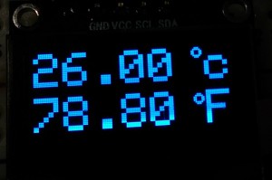
Temperature Sensor
Using a DS18B20 DALLAS temperature probe I have put the temperature inside the power box onto the display. Although it is not currently implemented in the firmware, it would be possible to have charge voltage temperature compensation built into the programming.
Lower Power Consumption
The biggest win from re-making this charge controller is that I was able to focus more on power consumption as a major factor. From the beginning I was trying to get it as low as possible. To do this I had to be careful on not only the components I used, but also on the programming and how long some components were left active.
For example:
During the day, the LCD LED backlight runs at a higher brightness, pulling around 3-4mA. At night, the LED is dimmed to reduce power consumption.
The current sensor is active for just a very short fraction of time every second, just long enough to get a reading. The sensor uses 10mA when active, so this was definitely necessary. At night it does not get probed for a reading.
The CPU frequency remains at 2MHz at all times, except when probing the temperature probe in which it returns to 16MHz for less than 1 second. The temperature only gets updated once every 60 seconds during the day and every 4 minutes at night.
The RGB LED showing the status at a quick glance uses a very low PWM output of around 5% duty. As a result the power consumption is very low, though I do not remember the exact amount of current. By not using PWM or using 100% PWM, the LED is unnecessarily bright and that just wastes power. At night, the LED flashes blue every time the CPU wakes up (4 second intervals) just to signal it is still alive and aware it is night time.
Total power consumption when the CPU is in sleep is just 2mA. That’s 3mA lower than the old charge controller when it was in sleep.
Images
-
-
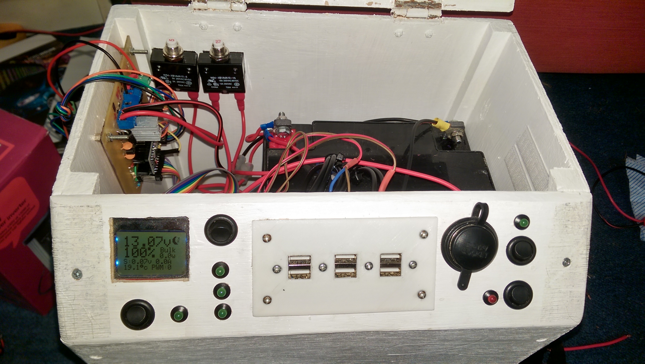
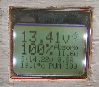
The LCD front panel.
-

-
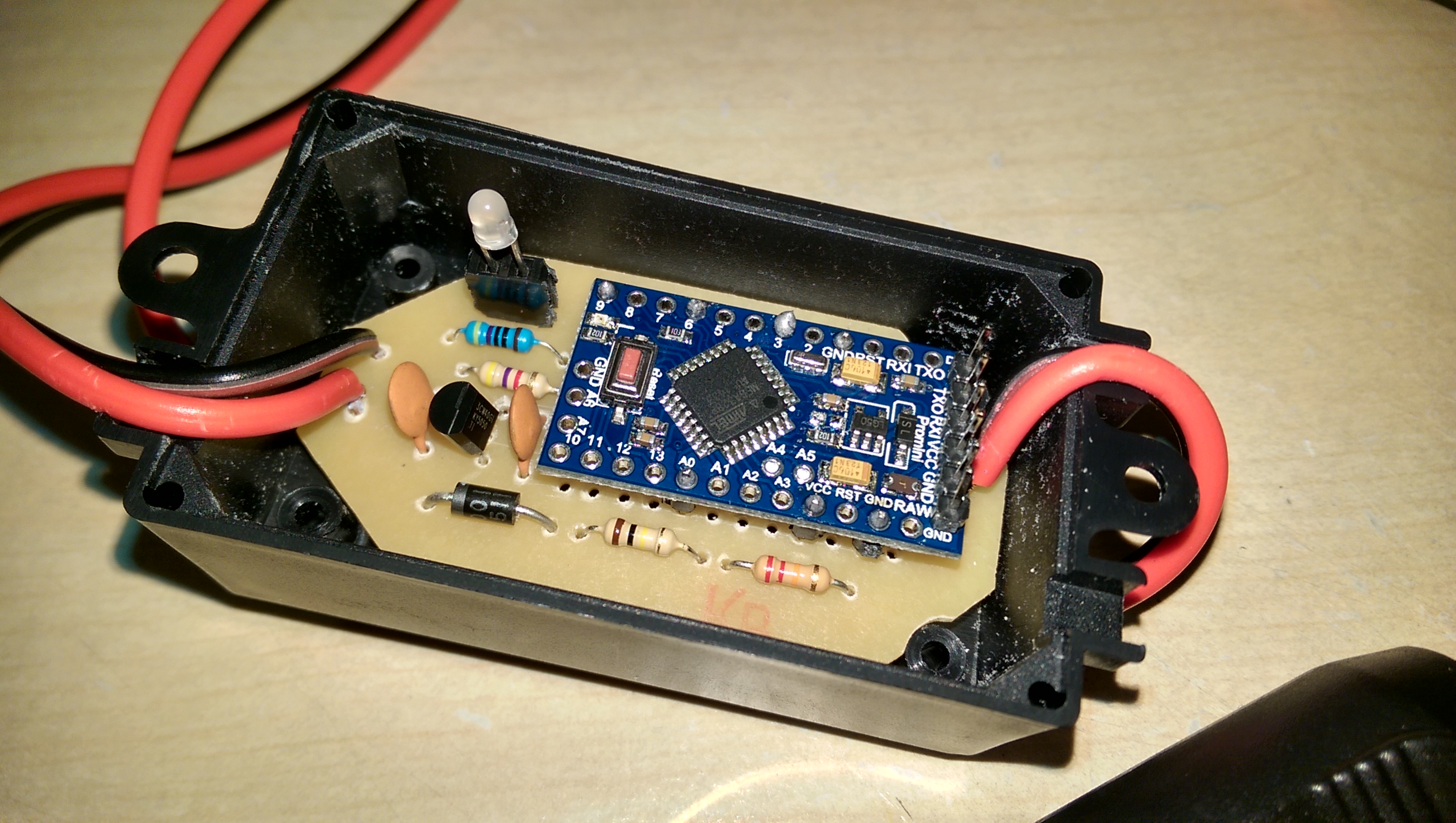
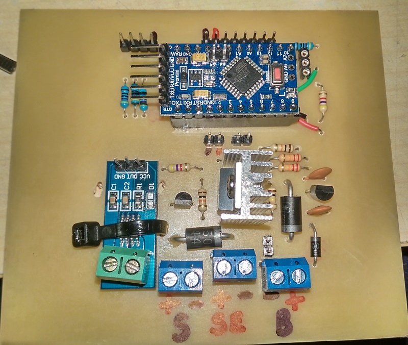
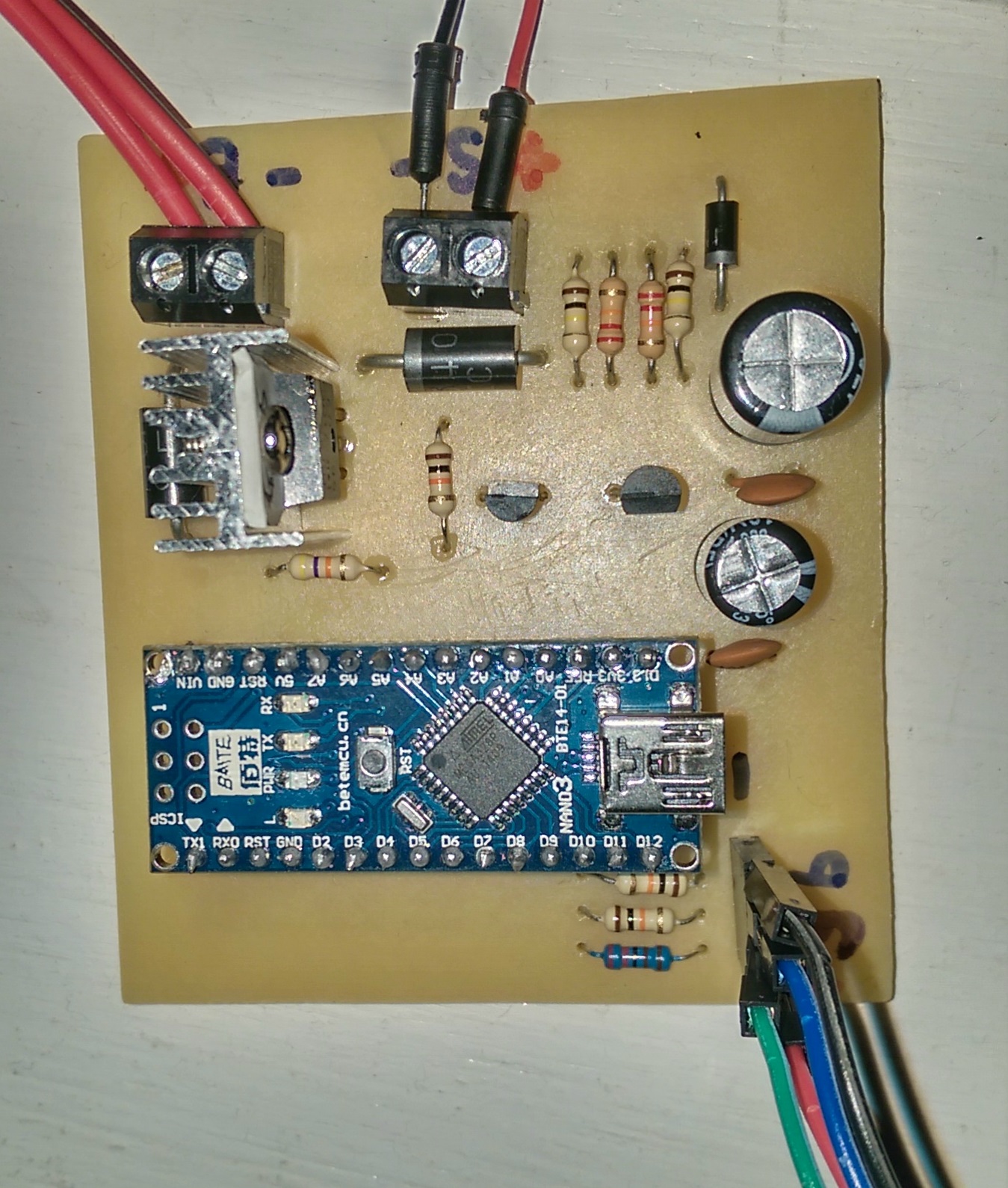
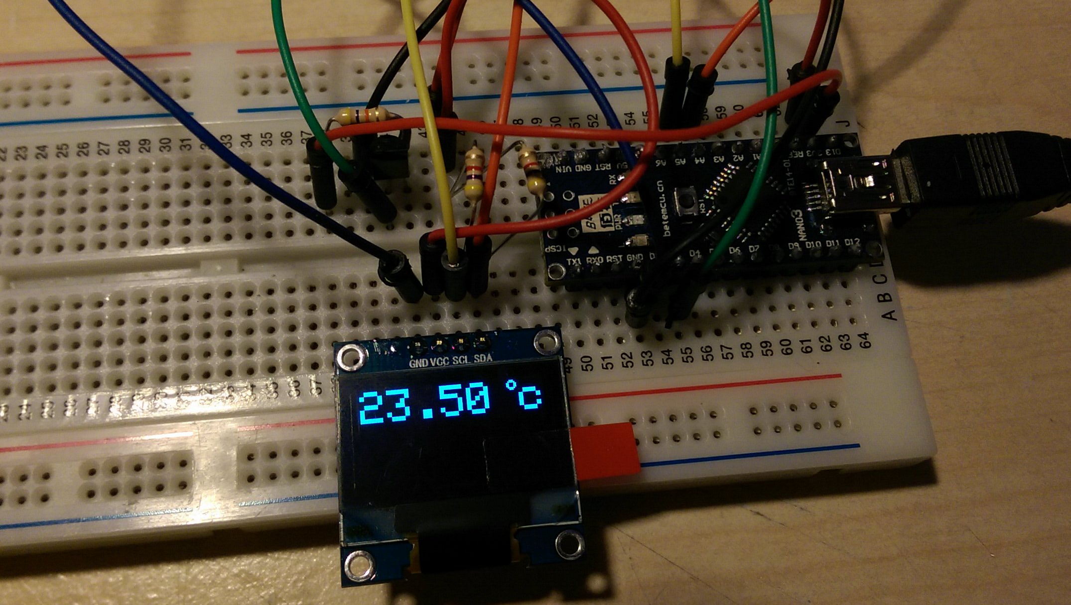
Testing the firmware with a programmer to allow easy updating.
-
-
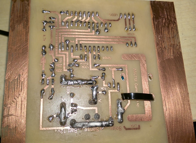
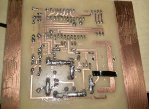
Solder covered traces to help with current flow.
-

-
-
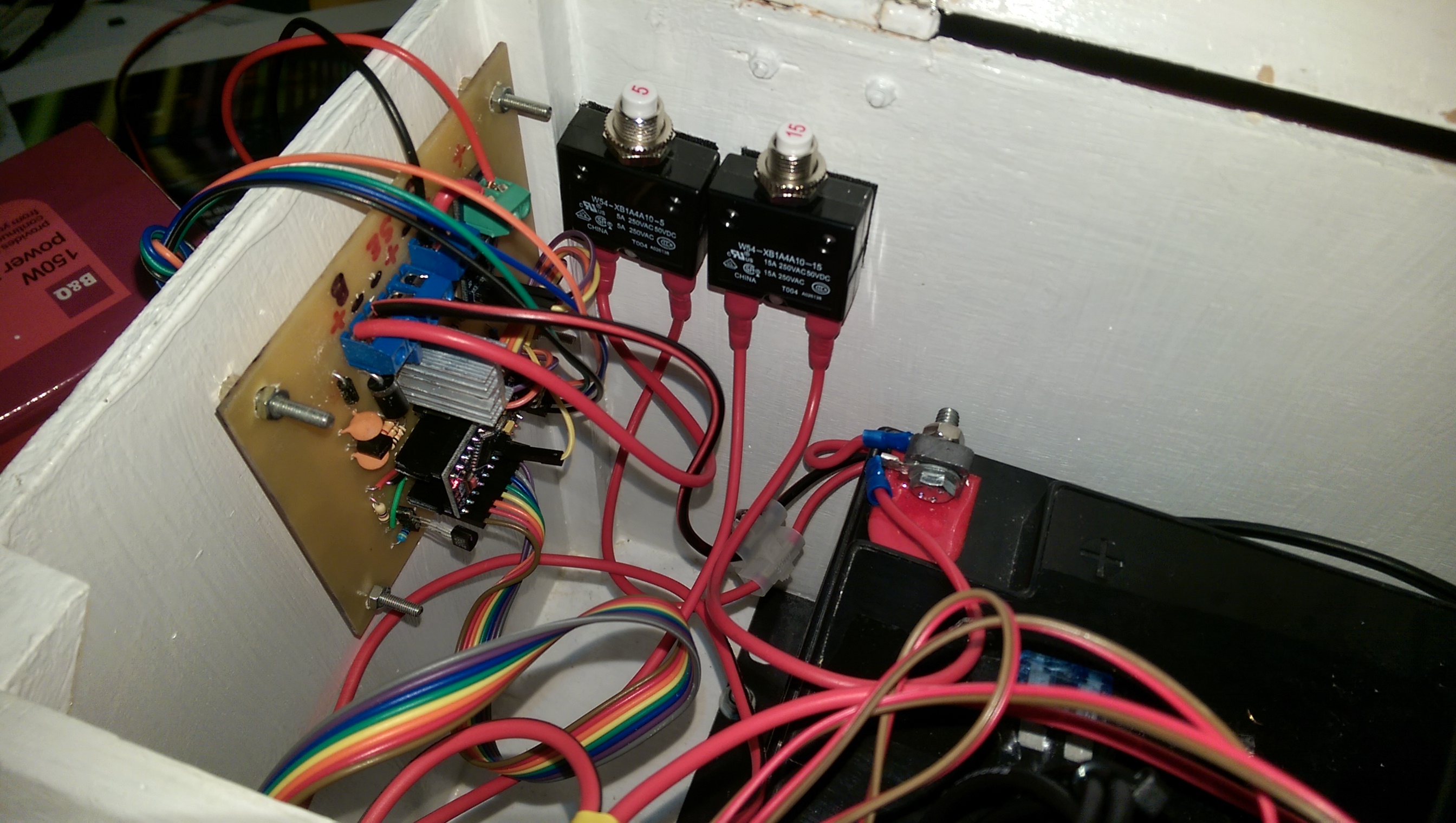
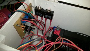
Some circuit breakers for protection.
-
-
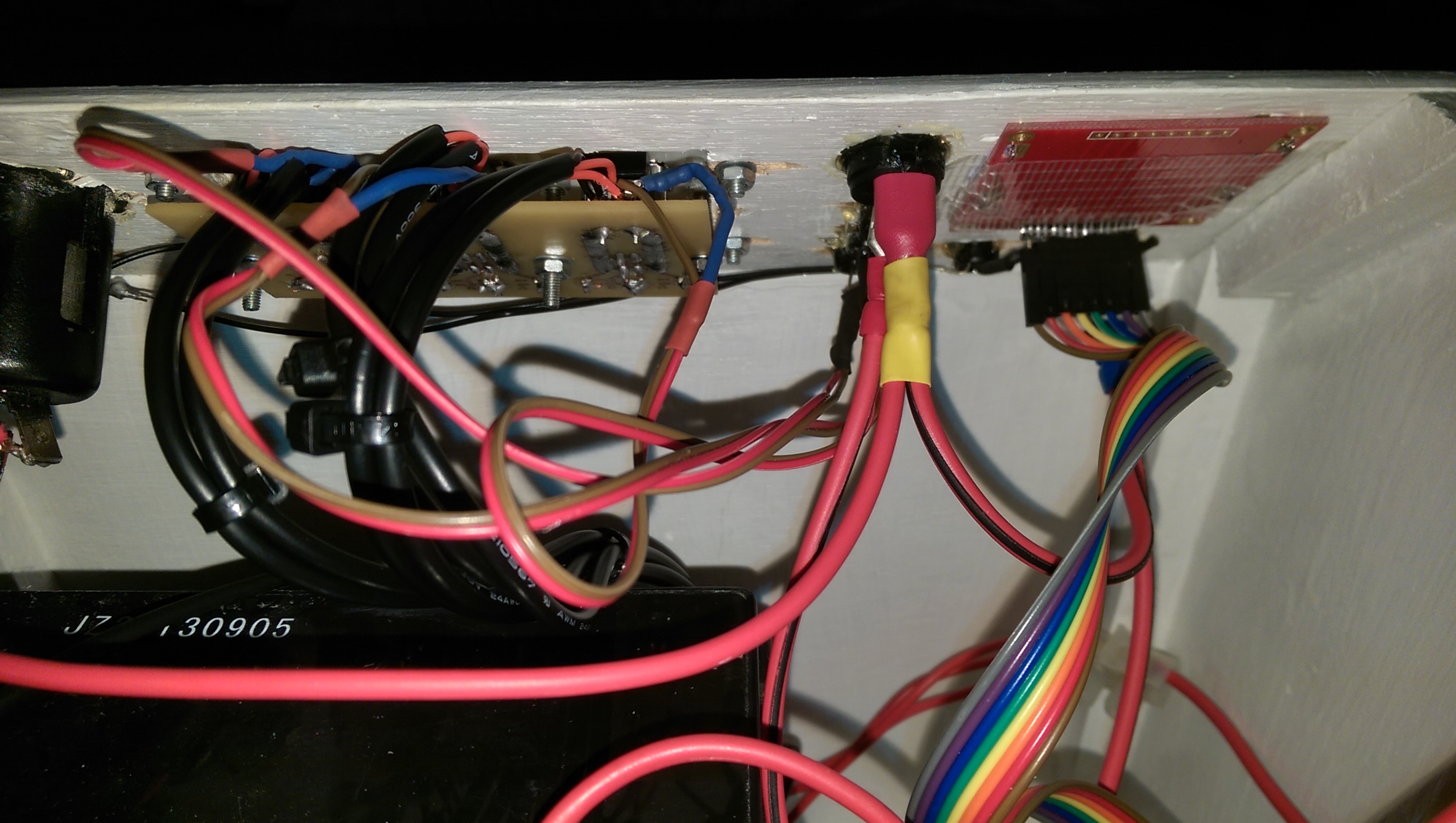
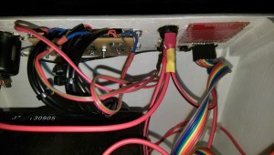
Safety and neatness through heat shrink.
-
-
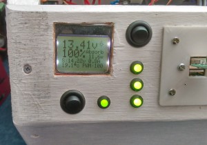
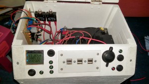
The final installation.
Specs
– 255 step PWM power control
– Solar panel and battery voltage aware
– Over/undershoot protection (software)
– Over-voltage (15.0v) protection (software)
– Automatic Bulk (14.5v) and float (13.5v) modes
– Solar panel to battery current display
– Temperature display
– RGB status LED
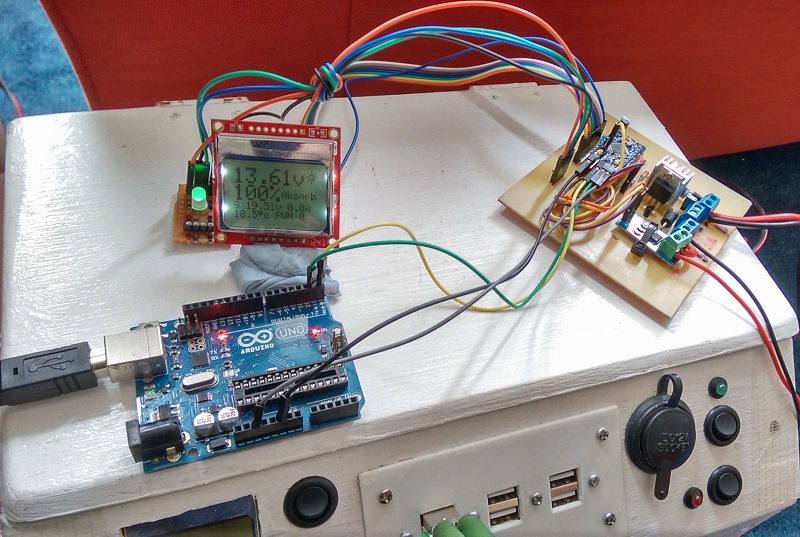
– LCD backlit display showing battery voltage, solar panel voltage, charge mode, current, watts, temperature and PWM %
– Voltage sense input
– Re-programmable with updated firmware
– 2mA at night, 7mA (15mA peak) during the day power consumption
Circuit Wizard Layout and Arduino Sketch
Download (14KB)
Apologies that there are no components listed for you to make this yourself. I do not have it to hand at the moment but I will update it here if I remember in the future.